


 Search
Knowledge Center
Comprehensive Guide to DC Isolator Switch Installation for Solar PV Systems
Learn where to install a DC isolator switch in solar PV systems, correct polarity wiring, DC arc prevention, IEC standards and how to select the right rating.
 July 08, 2026
Solar PV Safety Guide
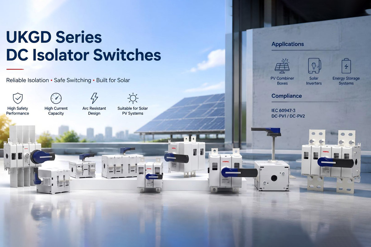
A DC isolator switch is an essential safety device in solar photovoltaic (PV) systems. It provides a manual disconnection point that allows installers and maintenance personnel to safely isolate DC power during inspection, troubleshooting, or emergency situations. Unlike AC circuits, DC circuits do not naturally pass through zero voltage points. As a result, DC arcs can continue after contacts separate, creating higher risks of overheating and equipment damage if the isolator is not specifically designed for DC applications. Choosing the correct DC isolator and installing it properly is critical for maintaining PV system safety, reliability, and compliance with electrical standards.
This guide explains where DC isolators should be installed, how to wire them correctly, how to prevent DC arc risks, and what factors should be considered when selecting a PV DC isolator switch.
Where to Place DC Isolators in PV System Architecture
The installation location of a DC isolator depends on the PV system design, inverter configuration, and local electrical requirements.
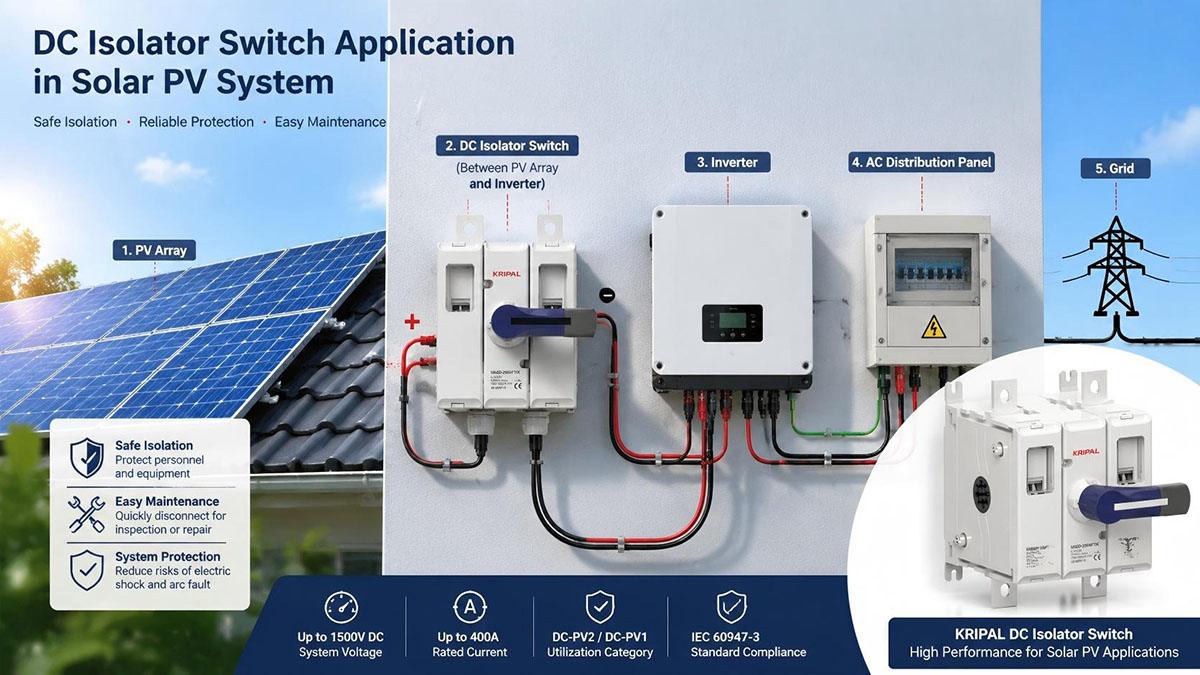
In most solar PV installations, a DC isolator is installed between the photovoltaic array and the inverter DC input. This allows the PV source to be safely disconnected before maintenance work is carried out on the inverter or downstream equipment.
For string inverter systems, whether an external DC isolator is required depends on the inverter design and local regulations. Many modern inverters include integrated DC switching, while some installations require additional external isolation points.
For larger commercial and utility-scale PV projects, DC isolators may also be installed at DC combiner boxes or sub-array locations. This allows individual sections of the PV system to be isolated without shutting down the entire installation.
Battery energy storage systems require separate DC isolation because battery circuits have different electrical characteristics from PV strings. Battery applications typically involve higher current levels and require DC isolators designed specifically for high-current switching.
KRIPAL High-Current DC Isolators
KRIPAL UKGD250 and UKGD400 DC isolators are designed for high-current DC applications, supporting up to 250A and 400A at 1000V DC. See the complete DC isolator switch range for solar and storage projects.
DC Isolator Switch Wiring and Polarity Requirements
Correct polarity wiring is one of the most important installation requirements for PV DC isolators.
A reversed polarity connection may damage sensitive equipment, including inverter input circuits, charge controllers, and battery management systems.
During installation, the positive conductor from the PV array should connect to the positive terminal of the isolator and continue to the positive input of the inverter. The negative conductor should remain connected through the negative terminals without crossing inside the switch.
Before energizing the system, installers should always verify polarity using a suitable measuring instrument and confirm that cable identification matches the system design.
PV conductor colors vary between countries and electrical standards. Red is commonly used for positive conductors and black for negative conductors in many PV installations, but installers should always follow local regulations and manufacturer requirements.
Recommended Installation Checks
- Confirm positive and negative terminal identification
- Verify polarity before closing the isolator
- Check terminal tightening torque according to manufacturer instructions
- Ensure DC cables maintain proper insulation protection
DC Arc Prevention During Load Switching
One of the biggest differences between AC and DC isolation is arc behavior. When AC contacts separate, the current naturally reaches zero during each cycle, helping extinguish the arc. DC circuits do not have this natural zero crossing, allowing arcs to continue for longer periods.
A PV DC isolator designed according to IEC 60947-3 uses appropriate contact spacing, insulation design, and arc extinguishing technology to safely interrupt DC circuits.
For applications where the isolator may need to disconnect current under load, a suitable utilization category such as DC-PV2 may be required depending on the system requirements.
Critical Safety Point
Using an AC-only isolator in a DC photovoltaic application is unsafe because the device may not have sufficient arc suppression capability. Compare the differences between AC isolator switches and dedicated DC-rated devices before specifying a product.
How to Choose the Right DC Isolator Switch
Selecting the correct DC isolator requires evaluating several important parameters.
Rated Voltage and Current
The isolator voltage rating must be equal to or higher than the maximum voltage of the PV system. Common PV applications include 600V DC, 1000V DC, and 1500V DC systems.
The current rating should match the maximum operating current of the circuit while considering environmental conditions, installation method, and applicable electrical standards.
Number of Poles
The required pole configuration depends on the system design.
Common configurations include:
- 2-pole isolators for positive and negative isolation
- Multi-pole isolators for multiple string isolation requirements
The correct configuration helps ensure complete and safe circuit disconnection.
Environmental Protection
Outdoor PV installations require consideration of:
- IP protection level
- UV resistance
- Temperature range
- Enclosure conditions
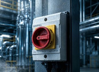
A suitable DC isolator should be selected according to the actual installation environment. For fully exposed rooftop and ground-mount projects, weatherproof designs such as the UKF series waterproof isolating switches simplify outdoor compliance.
DC Isolator Installation Best Practices
Correct installation is as important as correct product selection.
-
Size the DC Cables Correctly
Cable sizing should consider the maximum circuit current, temperature conditions, installation method, and local electrical regulations. Different regions may apply different calculation methods, so installers should always follow the requirements applicable to the project location.
-
Respect the Mounting Orientation
DC isolators should be installed according to the manufacturer’s instructions. Some products have specific mounting requirements because their internal arc extinguishing structures are designed for certain installation orientations.
-
Complete Pre-Commissioning Checks
Before commissioning the system, installers should check:
- Correct polarity connection
- Secure cable terminals
- Proper mechanical operation
- Clear ON/OFF indication
- Signs of overheating or damage
Relevant IEC Standards for DC Isolator Installation
The main standards related to PV DC isolation include:
| Standard | Application |
|---|---|
| IEC 60947-3 | Switches, disconnectors, and switch-disconnectors |
| IEC 60364-7-712 | Electrical installations for photovoltaic power supply systems |
| IEC 62109-2 | Safety requirements for PV power converters |
The exact requirements depend on the country, project design, and applicable electrical regulations.
Common DC Isolator Installation Mistakes
Using AC Isolators in DC Applications
AC-rated switches are not designed for photovoltaic DC interruption. Without proper arc extinguishing capability, they may fail during load switching.
The solution is to select a dedicated DC-rated isolator designed for PV applications.
Incorrect Polarity Connection
A reversed positive and negative connection may not damage the isolator itself, but it can cause serious damage to connected equipment when power is applied.
Always verify polarity before operation.
Selecting an Incorrect Rating
Using an isolator with insufficient voltage or current capability may cause overheating, contact damage, or premature failure.
The isolator should always be selected according to the actual system voltage, current, and environmental conditions.
Frequently Asked Questions (FAQs)
Can the same DC isolator be used for PV panels and battery systems?
Generally, separate isolators should be used. PV arrays and battery systems have different voltage and current characteristics and require devices designed for their specific applications.
What happens if DC polarity is reversed?
The isolator may still operate mechanically, but connected equipment such as inverters or controllers may be damaged when power is applied.
How often should DC isolators be inspected?
Inspection intervals depend on local regulations and operating conditions. Regular checks should include terminal condition, overheating signs, mechanical operation, and visible damage.
Conclusion
A DC isolator switch is a small but critical component in every solar PV system. Correct product selection, proper polarity wiring, and compliance with applicable standards help prevent arc failures, equipment damage, and safety risks.
By using correctly rated DC isolators and following manufacturer installation instructions, PV installers can improve system reliability and long-term performance.
KRIPAL provides IEC-compliant DC isolator solutions for photovoltaic and energy storage applications, supporting both standard and high-current DC switching requirements. Browse the full isolator switch range or contact our engineering team for project support.
Related Resources
Explore Knowledge Center >
Need a matching KRIPAL product?
Share voltage, quantity and destination. An engineer will reply with options and lead time.
