


 Search
Air Circuit Breakers (ACB) | 630A-7500A | Draw-Out Type | IEC 60947-2
High-Capacity Protection from a Professional Factory
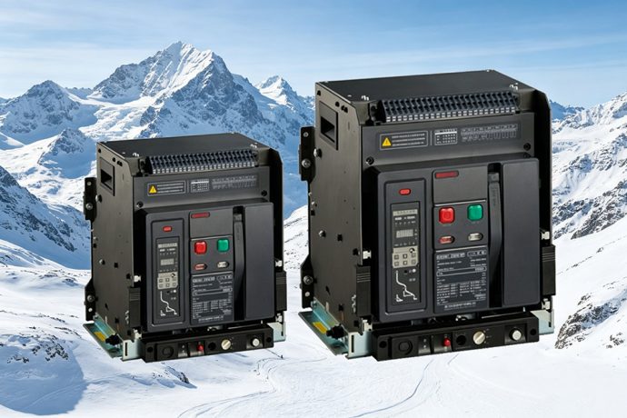
KRIPAL’s UKDW1 series air circuit breakers (ACBs) provide robust power distribution protection, offering rated currents from 630A to 7500A (Inm=1600/2500/4000/7500) per IEC 60947-2. The UKDW1 features advanced electronic trip units (IC5.0(M), IC7.0(3M), IC8.0(3H)) for real-time monitoring and comprehensive protection, including L, S, I, and G functions with configurable curves. The ACB utilizes a stored-energy spring mechanism for consistent, operator-independent closing speeds. Available in fixed (F) and draw-out (D) versions with 3P and 4P configurations, the UKDW1 supports field bus integration for remote measurement, control, and signaling within SCADA systems. Certified to IEC 60947-2, KRIPAL ACBs serve as reliable incoming and bus-coupler devices for industrial plants, data centers, and large-scale infrastructure projects.
Get A Quote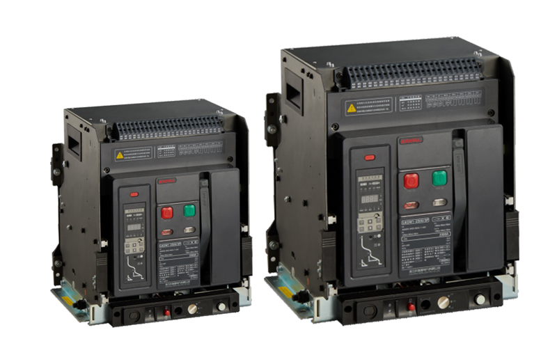
ACB Selection for Main Switchboard Incomer Protection
An air circuit breaker is the highest-capacity low-voltage protection device, rated for continuous currents up to 7500A and robust fault currents. The ACB uses atmospheric air as the arc extinguishing medium, with the arc being drawn into a segmented arc chute where it is split, cooled and deionized until extinction. The stored-energy spring mechanism ensures consistent contact closing speed and force regardless of whether the operator is manual (a charging handle) or motorized, eliminating the risk of contact welding due to a slow manual close. The electronic trip unit (IC5.0(M), IC7.0(3M), IC8.0(3H)) provides the most comprehensive protection and measurement capabilities of any LV circuit breaker, transforming the ACB from a simple protection device into an intelligent power monitoring node in the facility’s electrical network. This selection guide covers frame size, trip unit functions, communication options and mounting configuration.
UKDW1 ACB Series Technical Specifications
Frame Size and Current Rating Selection
The UKDW1 is available in four frame sizes: Frame 1 (Inm=1600, 200-1600A), Frame 2 (Inm=2500, 630-2500A), Frame 3 (Inm=4000, 2500-4000A) and Frame 4 (Inm=7500, 4000-7500A). Frame size defines physical dimensions, busbar interfaces, and maximum ratings. The electronic trip unit is field-adjustable without hardware changes. For a 2000 kVA transformer (2887A at 400V), a Frame 3 3200A ACB set to 0.9 In (2880A) provides overload margin per IEC 60076 while protecting secondary cables. Ratings must account for enclosure internal temperatures exceeding room ambient due to busbar heat.
LSIG Protection Functions and Coordination
The UKDW1 electronic trip unit (IC5.0(M), IC7.0(3M), IC8.0(3H)) provides four adjustable protection functions. Long-time (L) protects against sustained overloads with I squared t thermal memory (0.4-1.0 In pickup). Short-time (S) provides selective coordination with downstream MCCBs (1.5-10 times L pickup, 0.1-0.4s delay). Instantaneous (I) clears bolted faults (2-15 times In with OFF option). Ground-fault (G) detects earth faults (0.2-1.0 In pickup, 0.1-0.4s delay) using residual current or a separate neutral sensor.
Power Metering and Communication Integration
The UKDW1 trip unit features an integrated power quality meter displaying phase/neutral currents, voltages, power, power factor, frequency, 4-quadrant energy, and THD. Measurement accuracy meets Class 1 per IEC 61557-12 for sub-billing. Communication supports field bus integration for remote measurement, adjustment, control, and signaling (Modbus RTU RS-485 and optional protocols). It stores the last 20 trip events with time stamps, fault types, and pre-trip values for post-fault analysis.
Drawout Configuration and Maintenance
The UKDW1 drawout version features a racking mechanism with three positions: CONNECTED, TEST (power isolated, control active for configuration), and ISOLATED. Safety shutters cover fixed contacts during rack-out to provide IP2X protection. A single electrician can rack and remove the ACB in under 5 minutes, avoiding the 2-3 hours required for fixed bolted units. Spare units can be kept in switch rooms and swapped during scheduled maintenance windows to minimize downtime.
Specify ACBs for Your Main Switchboard
- Protection Coordination Study: Our engineers design a complete LSIG protection scheme for your power distribution network with UKDW1 settings.
- Power Monitoring Integration: Request the Modbus register map and configuration guide for integrating UKDW1 measurements into your BMS or SCADA.
- OEM Switchboard Supply: Source UKDW1 ACBs pre-configured with trip unit settings and factory witness-tested for your switchboard project.
Main Incomer Protection for Critical LV Switchboards
KRIPAL UKDW1 air circuit breakers are the primary protection and control devices at the main LV switchboard level in large industrial, commercial and infrastructure installations. From the incoming ACB on a factory main switchboard to the bus-coupler ACB in a hospital’s dual-supply switchboard, the UKDW1 provides the highest level of protection coordination, power monitoring and remote control capability available in a low-voltage circuit breaker.
Industrial Plant Main Incoming & Hospital Dual-Supply ACBs
A manufacturing plant with a 2500 kVA supply transformer uses a UKDW1 drawout ACB as the main incoming device. The LSIG protection coordinates with the transformer’s damage curve per IEC 60076-5 and downstream MCCBs. Integrated meters track power consumption and harmonics via Modbus for ISO 50001 reporting, and during annual shutdowns, the ACB is racked to the ISOLATED position for inspection without disconnecting busbars. Similarly, a hospital’s essential supply uses two incomer ACBs and a third bus-coupler ACB. Under normal operation, incomers are closed and the bus-coupler is open; if a utility fails, an incomer opens, the bus-coupler closes, and a PLC manages the transfer. The bus-coupler’s short-time delay coordinates with the incomers, and its instantaneous protection is set to OFF to prevent a total facility blackout.
Data Center UPS Output Distribution ACB
A data center’s UPS output switchboard uses UKDW1 ACBs as feeder devices to each server room power distribution unit (PDU). The ACB’s power meter measures PDU energy consumption and reports to the DCIM system for colocation customer billing. Harmonic distortion measurement monitors server power supply harmonic current injection, alerting the facilities team if THD exceeds UPS capabilities due to failing capacitors. Additionally, the event log captures trip events with pre-fault current and voltage waveforms, enabling root cause analysis of server room power outages.
Commercial High-Rise Bus Riser ACB
A 40-story commercial tower uses UKDW1 ACBs at the main switchboard to feed vertical busbar risers supplying each floor’s distribution board. The ACB’s LSIG settings coordinate with floor MCCBs, and ground-fault protection detects arcing faults caused by insulation degradation in aging busbars. Modbus communication reports riser currents to the BMS; if a current drops near zero due to an MCCB trip or connection failure, the BMS generates an alarm for immediate investigation.
Generator Synchronizing Circuit Breaker
A standby power system with multiple generators operating in parallel uses UKDW1 ACBs as generator circuit breakers. The trip unit measures generator output voltage, frequency, and phase angle, allowing the synchronizing controller to match outputs to the busbar before closing. The motor operator closes the ACB within 50ms of receiving the command for minimal transient current. Furthermore, power meters measure kW and kVAr output, enabling load-sharing controllers to adjust fuel governors and AVRs for equal active and reactive power distribution.
Engineer Your Main Switchboard Protection
- Protection and Coordination: Our power systems engineers design the complete ACB protection scheme with UKDW1 settings verified for your network.
- FAT Witness Testing: Schedule a factory acceptance test of your UKDW1 ACBs with secondary injection verification of all protection functions.
- OEM Partnership: Dedicated ACB production scheduling and JIT delivery for switchboard manufacturers with project-based requirements.
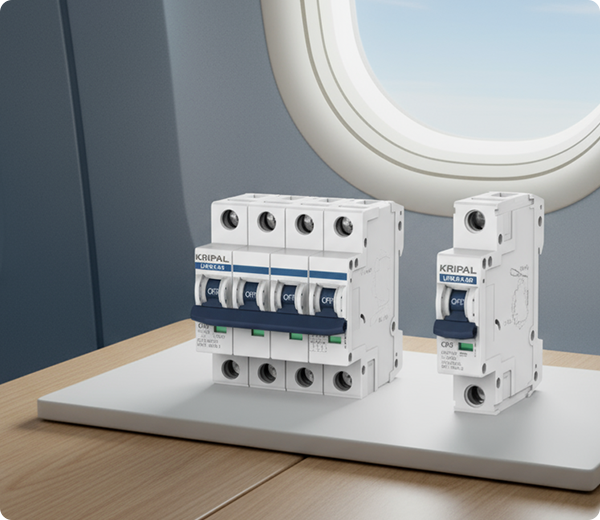
KRIPAL ACB Manufacturing: Engineered for Ultimate Protection
KRIPAL air circuit breakers are manufactured in a dedicated assembly hall with climate-controlled environment for the electronic trip unit calibration. Each ACB undergoes a complete functional test sequence including contact resistance measurement, trip unit calibration across all protection functions, and mechanical endurance cycling for global main switchboard and power distribution applications up to 7500A.
Climate-Controlled Assembly and Calibration Environment
ACB assembly is performed in a controlled environment. This environmental control is essential for the precision calibration of electronic trip units where temperature drift in reference components could affect protection accuracy at the microsecond level.
Electronic Trip Unit Multi-Function Calibration
Each microprocessor-based trip unit (IC5.0(M), IC7.0(3M), IC8.0(3H)) is calibrated for the full protection suite: long-time delay (L), short-time delay (S), instantaneous (I), and earth fault (G). Calibration is performed by injecting precision current signals into the trip unit’s sensing inputs and verifying trip times at multiple points on each protection curve against the published time-current characteristics.
Draw-Out Cassette and Main Contact Cluster Assembly
The draw-out mechanism incorporates silver-plated copper contact clusters with multiple independent contact fingers per pole for current sharing. Each cluster is measured for individual finger contact resistance and total cluster resistance. The cassette racking mechanism is tested for insertion/withdrawal force and for correct operation of the position indicator (CONNECTED, TEST, ISOLATED).
End-of-Line Functional Test Sequence
Every ACB undergoes a complete end-of-line test: main contact resistance (four-wire at 100A DC), dielectric withstand between open contacts and between poles, trip unit functional test on all protection functions, mechanical endurance with stored-energy mechanism, and undervoltage release and shunt trip verification.
Distributor and Project Stock Programs for ACBs
KRIPAL supports project-specific delivery scheduling for ACBs with agreed lead times. Critical spare parts and interchangeable trip units are maintained in stock for rapid shipment to minimize switchboard downtime during maintenance or retrofit projects.
Private Label and OEM Branding for ACBs
Custom nameplates, OEM trip unit firmware branding (where applicable), and project-specific documentation packages are available. KRIPAL supports the supply of ACBs with customer-specified protection settings pre-configured at the factory for panel builder integration.
Multi-Region Certification and Compliance Support
Compliance documentation including IEC 60947-2 is provided. Type test certificates from accredited laboratories are available for the complete UKDW1 ACB range, supporting switchboard manufacturers’ conformity assessments.
Direct Technical Access to KRIPAL ACB Engineers
Your technical team communicates directly with the ACB design and production engineers. Application questions including selectivity studies, busbar connection details, and arc flash calculations receive answers within 24 hours during China business hours.
Frequently Asked Questions
Explore FAQ >Recent Blog
Explore Blog >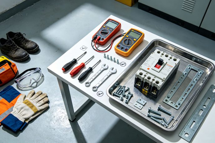
How to Install an ACB?
Learn how to install an ACB safely with our step-by-step guide. Covers preparation, electrical connections, testing, and maintenance tips.
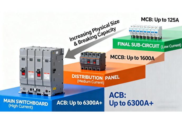
What MCB, MCCB and ACB Stand For and How They Differ in Use
Confused by acronyms? Compare MCB vs MCCB vs ACB. Learn the key differences in amperage, breaking capacity, and applications to select the right breaker.
What are the Difference of MCCB and ACB?
Compare MCCB and ACB on breaking capacity, cost, maintenance & applications, learn core differences to select the right circuit breaker.
Which Gas Used In ACB?
Learn which gas used in ACB systems for insulation & arc extinction. Compare air, SF6, CO2, and eco-friendly gases for air circuit breakers.
Direct from Manufacturer
How Can We Assist You?
Tell us a bit more so we can route your request to the right engineer. Get factory-direct pricing and custom specifications within 24 hours.
