Search
Type 1 2 DC Surge Protectors for Photovoltaic Systems | 600V-1500V | IEC 61643-31
KRIPAL Modular DC Surge Protective Devices
KRIPAL manufactures DC surge protective devices (DC SPDs) in the UKD2 series specifically designed for photovoltaic array DC-side lightning and switching surge protection. Available in Type 1+2 combined and Type 2 classifications per IEC 61643-31, these SPDs protect PV inverters, combiner boxes and DC distribution equipment against transient overvoltages induced by nearby lightning strikes and utility grid switching events. The UKD2 features metal oxide varistor (MOV) technology with a maximum continuous operating voltage of up to 1500V DC, a nominal discharge current of 20kA (8/20 microsecond waveform) and a maximum discharge current of 40kA per pole. A pluggable module design with built-in thermal disconnector and visual fault indicator allows hot-swap replacement of a degraded module without disconnecting the PV circuit, and an optional remote signaling contact (changeover) integrates with the inverter or plant SCADA for centralized SPD status monitoring. Certified to IEC 61643-31 for PV system SPDs and EN 50539-11, the UKD2 is available in 2P, 3P and 4P configurations with common and differential mode protection wiring schemes for grounded and ungrounded PV arrays.
Get A Quote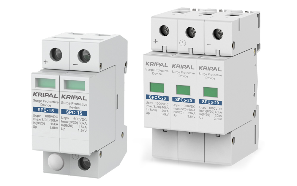
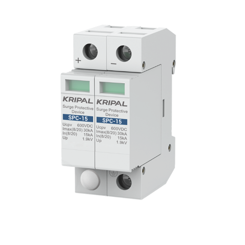

SPC-15 DC Surge Protector 2Pole 600V DC SPD 15kA~30kA Surge Arrester
The SPC-15 2p Surge Arrester provides equipotential bonding at the boundaries of LPZ1, LPZ2, and LPZ3 zones.
Ask a QuoteDC SPD Application and Selection for Solar DC Circuits
A DC surge protective device diverts lightning-induced transient overvoltages from the PV DC conductors to earth, protecting the inverter power electronics, DC cabling and combiner box components from insulation breakdown and semiconductor damage. Unlike AC SPDs that operate at 50/60 Hz with a natural zero-crossing for follow-current extinction, DC SPDs must extinguish any follow current from the PV array without a zero-crossing point, which requires a higher Uc (maximum continuous operating voltage) rating and a DC-specific varistor formulation. This selection guide covers SPD type, voltage protection level, discharge capacity and wiring configuration to match your PV system’s lightning risk zone and inverter surge withstand capability.
UKD2 DC SPD Series Technical Specifications
SPD Type Selection per Lightning Risk Zone
IEC 62305-4 defines lightning protection zones (LPZ) that determine which SPD type is required. At the boundary between LPZ 0A (direct strike zone) and LPZ 1, a Type 1 SPD rated for 10/350 microsecond impulse current (Iimp) is needed. At the LPZ 1/LPZ 2 boundary where the PV inverter is located, a Type 2 SPD rated for 8/20 microsecond impulse current (In/Imax) is sufficient. The UKD2 Type 1+2 combined unit satisfies both requirements in a single device, simplifying the SPD coordination in PV combiner boxes that span multiple lightning protection zones. For rooftop PV installations in urban areas with existing building lightning protection, a Type 2 UKD2 is typically adequate at the inverter DC input.
Voltage Protection Level and Inverter Coordination
The voltage protection level (Up) of the SPD must be lower than the impulse withstand voltage (Uw) of the PV inverter DC input by a safety margin of at least 20 percent. UKD2-600V DC units achieve Up of 2.5kV, which is below the typical 4kV Uw of string inverters in the 10-100 kW class. For central inverters with 6kV or 8kV Uw, the UKD2-1000V unit with Up of 3.8kV provides adequate margin. The connecting leads between the SPD and the DC busbars must be kept shorter than 0.5 meters total (combined length of both leads) because the lead inductance adds approximately 1kV per meter to the effective protection level during an 8/20 microsecond surge, potentially negating the SPD’s protection if leads are too long.
Wiring Configuration for Grounded and Ungrounded Arrays
The UKD2 supports three standard PV SPD wiring configurations. For a grounded PV array (one pole referenced to earth), a 2P SPD wired in common mode (L+ to PE, L- to PE) protects both conductors against earth-referenced surges. For an ungrounded (floating) PV array, a 3P SPD adds a differential mode protection element (L+ to L-) that clamps surges appearing between the positive and negative conductors without an earth reference. For bipolar arrays (plus, minus and neutral/center-tap), a 4P SPD protects all three conductors to earth plus differential protection between each pair. The pluggable module design allows field reconfiguration by swapping the internal MOV modules without replacing the base unit.
Pluggable Module and End-of-Life Indication
Each UKD2 protection element is housed in a pluggable module with a mechanical coding key that prevents insertion of an incorrectly rated replacement module. A built-in thermal disconnector opens the circuit when the MOV degrades to end-of-life (typically after absorbing multiple surges that gradually increase the MOV leakage current and temperature), and a green-to-red visual indicator on the module face shows the status at a glance. The base unit includes a 3-pole changeover contact (common, normally open, normally closed) rated 250V AC 0.5A for remote signaling to the inverter, combiner box monitoring system or plant SCADA. When a module is replaced, the indicator resets to green and the remote contact returns to normal, with no tools required for module extraction except a standard flat-blade screwdriver to release the locking tab.
Specify DC Surge Protection for Your PV System
- Risk Assessment Tool: Submit your site GPS coordinates and array configuration for a lightning risk zone assessment with recommended SPD type and installation points.
- SPD Coordination Study: Request a cascaded SPD scheme showing UKD2 protection levels coordinated with your inverter internal SPD and AC-side surge protection.
- Replacement Module Stock: Order spare pluggable modules with your initial shipment for 5-year on-site spares coverage without minimum order quantities.
Protecting Solar Inverters from Surge Damage Across All PV System Scales
KRIPAL UKD2 DC surge protective devices are installed at every DC distribution level in a photovoltaic system where transient overvoltage protection is specified by the lightning risk assessment. From the array junction box to the inverter DC input and the battery storage DC bus, these SPDs form a coordinated cascaded protection scheme that diverts surge energy to earth before it reaches sensitive power electronics.
PV Array Junction Box Lightning Protection
In ground-mount PV installations in lightning-prone regions (central Florida, Southeast Asia, sub-equatorial Africa), UKD2 Type 1+2 SPDs are installed in the array-level junction box where string cables are combined before the DC feeder cable runs to the inverter shelter. A direct lightning strike to the PV module frames induces a conducted surge on the DC cables through capacitive coupling between the module frame and the cells, and the Type 1 10/350 microsecond impulse rating of the combined SPD handles this worst-case surge waveform without damage. The pluggable module allows replacement after a major lightning event without requiring an electrician to disconnect and reconnect DC cables inside the energized junction box.
Inverter DC Input Surge Protection
String inverters and central inverters typically specify an external DC SPD at the DC input terminals, supplementing the inverter’s internal AC-side SPD. The UKD2-1000V Type 2 SPD is DIN-rail mounted inside the inverter DC disconnect enclosure, with leads kept shorter than 0.5 meters to the DC busbars to minimize the additional voltage drop from lead inductance during a surge. The remote signaling contact is wired to the inverter’s digital input, so the inverter controller can log an SPD fault event and alert the O&M provider to dispatch a technician for module replacement before the next thunderstorm season begins.
Battery Storage DC Bus Protection
Utility-scale BESS containers with DC bus voltages of 1000-1500V install UKD2 DC SPDs at the battery rack DC busbar and at the PCS DC input. Although battery containers are metallic and provide a degree of shielding, the long DC cable runs between battery racks and the PCS (up to 20 meters in a 40-foot container) act as antennas that couple induced surges from nearby lightning strikes into the DC bus. The UKD2 3P configuration with differential mode protection prevents surge voltage from appearing between the positive and negative DC bus conductors, which would otherwise be impressed directly across the PCS IGBT modules with a withstand voltage of only 1.7-3.3kV.
EV Charging Station DC Power Module Protection
DC fast chargers with distributed power modules in outdoor cabinets use UKD2 DC SPDs at each power module DC input to protect the silicon-carbide (SiC) MOSFET switching devices, which have a lower avalanche energy rating than traditional silicon IGBTs and are more susceptible to surge-induced overvoltage damage. The compact DIN-rail form factor of the UKD2 fits inside the power module enclosure alongside the DC input filter capacitors and pre-charge circuit, with the remote signaling contact integrated into the charger management system for centralized SPD health monitoring across all dispensers in a charging plaza.
Off-Grid Solar Mini-Grid DC Distribution
Rural electrification mini-grids in developing countries use UKD2 DC SPDs to protect the DC distribution network (typically 48V or 110V DC) that feeds power from a central solar-battery station to village households. The long overhead DC distribution lines (up to 2 km) are exposed to induced surges from nearby lightning strikes, and without SPDs at the source and at each consumer connection point, a single storm can destroy the DC-DC converters in dozens of household energy meters. The UKD2-250V unit with its low Up of 1.2kV and 20kA discharge capacity provides cost-effective protection for these community-scale DC infrastructure assets.
Protect Your PV Investment with Coordinated Surge Protection
- Site-Specific SPD Scheme: Submit your site lightning flash density map and we design a coordinated SPD scheme with UKD2 devices at every required protection zone boundary.
- Type-Test Certification: Obtain IEC 61643-31 and EN 50539-11 test reports for your project insurance underwriter and AHJ permit package.
- Spare Module Program: Pre-purchase replacement pluggable modules at project start for guaranteed 10-year availability of the exact MOV batch used in your installed SPDs.
KRIPAL DC SPD Production: Engineered to Absorb Lightning Strikes
KRIPAL DC surge protective devices are manufactured in a dedicated MOV production facility where zinc oxide varistor discs are formulated, pressed, sintered, and metallized in-house. The complete SPD assembly including thermal disconnector and status indicator undergoes 8/20 microsecond impulse testing on sample units from every production lot for global PV system lightning protection.
Zinc Oxide Varistor Disc Production In-House
KRIPAL formulates ZnO varistor powders with controlled dopant additions (Bi2O3, Sb2O3, MnO, CoO) for optimized nonlinear V-I characteristics. Discs are pressed to precise density, sintered in tunnel kilns with computer-controlled temperature profiles, and metallized with silver electrodes via screen printing, enabling consistent clamping voltage performance batch-to-batch.
Thermal Disconnector Assembly and Verification
Each SPD incorporates a soldered thermal disconnector designed to open at a specific temperature threshold when the MOV reaches end-of-life. The solder alloy composition and joint geometry are verified on sample units from each production lot using a calibrated hot-air test to confirm disconnection within the safety time window defined by IEC 61643-31.
8/20 Microsecond Impulse Testing Per Batch
A computer-controlled 8/20 microsecond combination wave generator capable of 40kA peak current is used to test sample SPDs from every production batch. Residual voltage at nominal discharge current (In) and maximum discharge current (Imax) is measured and recorded against the published protection level (Up) for full production lot traceability.
Status Indication and Remote Signaling Assembly
Visual status indicators (green/red window) and volt-free changeover contacts for remote monitoring are assembled and tested per unit. The mechanical flag mechanism that triggers on thermal disconnection is verified for positive operation in all mounting orientations (vertical, horizontal, inverted) before final packaging.
Distributor Stock Holding Programs for DC SPDs
KRIPAL supports distributor inventory programs with agreed stock levels for standard DC SPD models. Shipments are planned based on demand data, with scheduled replenishment to maintain stable supply and consistent fill rates.
Private Label and OEM Branding for DC SPDs
Laser-marked part numbers aligned with your catalog, OEM-branded packaging, and customized multilingual instruction sheets are available. Unbranded supply is provided upon request for private label production of DC SPDs.
Multi-Region Certification and Compliance Support
CE, UKCA, and IEC 61643-31 EN 61643-31 compliance documentation is provided according to target export markets. Technical documentation files are maintained and updated in line with evolving regulatory requirements, supporting PV lightning protection system conformity assessments.
Direct Technical Access to KRIPAL Production Engineers
Your technical team communicates with the engineers who designed and tested your DC SPDs, not a distributor’s sales engineer reading from a catalog. Application questions receive answers within 24 hours during China business hours.
Frequently Asked Questions
Explore FAQ >PV arrays are large outdoor metallic structures that attract lightning. Induced surges on DC cabling can destroy inverter MPPT electronics in microseconds. A DC SPD diverts this energy to ground, protecting assets worth thousands for the cost of a single protection device.
DC SPDs must extinguish DC follow-current without the natural current zero-crossing that AC SPDs rely on. They are tested to IEC 61643-31 (PV-specific), not generic AC standards. An AC SPD on a DC PV circuit will fail to clear the follow-current and may short permanently.
Replace when the visual indicator changes from green to red, signaling the thermal disconnect has activated. SPDs with remote contacts also trigger an electrical alarm signal. After a known direct lightning strike, inspect all SPDs even if indicators show green.
Select Ucpv (maximum continuous operating voltage) at least 1.2 times the PV array Voc at minimum temperature. For a typical residential string at Voc approximately 450V, a 600V DC SPD provides sufficient margin. For 1500V utility systems, select 1500V DC SPDs.
For installations in high-lightning areas (Ng above 2.5): yes. Install Type 1 2 SPDs at the array combiner box and Type 2 SPDs at the inverter DC input. For low-lightning areas, Type 2 SPDs at the inverter may be sufficient. Always follow local electrical code requirements.
Direct from Manufacturer
How Can We Assist You?
Tell us a bit more so we can route your request to the right engineer. Get factory-direct pricing and custom specifications within 24 hours.