Search
Zero Current Transformers ZCT for Earth Leakage Relays | 35mm-210mm ID
In-House Production for Precise Fault Monitoring
KRIPAL manufactures zero-sequence current transformers (ZCTs) for earth leakage detection in low-voltage power distribution systems, designed to work with the UKE1 earth leakage relay and the UKM1EL ELCB MCCB. The ZCT is a toroidal current transformer through which all phase conductors (and neutral, if applicable) are passed, producing a secondary output voltage proportional to the vector sum of the primary currents which is zero in a healthy circuit and non-zero when current leaks to earth. KRIPAL ZCTs are available with internal diameters from 35mm to 210mm to accommodate conductor cross-sections from small control wiring to multiple 240 sq mm power cables, with sensitivities suitable for earth leakage detection from 30mA to 30A. The ZCT core is manufactured from high-permeability grain-oriented silicon steel for standard sensitivity applications (1A and above) or mu-metal (nickel-iron alloy) for high-sensitivity applications (30mA-300mA) where the core must produce a measurable secondary voltage from very low primary residual currents. Each ZCT is supplied with a shielded twisted-pair secondary cable (standard 2 meters, extendable to 10 meters) and mounting brackets for secure installation on busbars or cable trunking. The ZCT housing is molded from flame-retardant ABS with a hinged design that allows retrofitting around existing conductors without disconnecting them, secured by stainless steel screws.
Get A Quote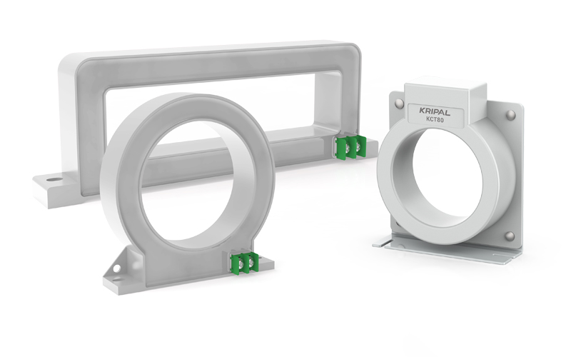
How to Select a Zero Current Transformer
A zero-sequence current transformer (also called a residual current transformer or core-balance CT) is the sensing element in an earth leakage protection system. It works on the principle that the vector sum of the currents flowing in all the conductors passing through the ZCT aperture is zero when there is no earth fault (Kirchhoff’s current law: the sum of currents entering a node equals the sum leaving). When current leaks to earth, this balance is disturbed, and the resulting net magnetic flux induces a voltage in the ZCT secondary winding proportional to the earth leakage current. The ZCT is a passive device with no electronics and no auxiliary power supply, making it inherently reliable with a service life exceeding 30 years when correctly installed. This selection guide covers ZCT internal diameter, core material, sensitivity and installation requirements.
ZCT Series Technical Specifications
Internal Diameter Selection by Conductor Size
The ZCT internal diameter must accommodate all the circuit conductors with adequate clearance for their insulation. As a rule, the total cross-sectional area of all conductors including insulation should not exceed 40 percent of the ZCT aperture area to ensure the conductors can be centered and the magnetic field is uniform. For a 63A circuit with 16 sq mm conductors (4.1mm diameter), a 35mm ZCT is adequate. For a 400A circuit with 185 sq mm conductors (17mm diameter) on a 4-pole system, a 110mm ZCT is required. For a 1600A circuit with 4x 240 sq mm conductors per phase (total 12 conductors plus neutral), a 210mm ZCT is required. KRIPAL provides a ZCT sizing chart in the UKE1 and UKM1EL datasheets listing the recommended ZCT diameter for standard cable sizes and circuit configurations. The ZCT must be installed with all conductors passing through in the same direction, with the load side of the ZCT facing the protected equipment.
Core Material and Sensitivity Matching
The ZCT core material determines the minimum detectable earth leakage current. Silicon steel (M4 grade, initial permeability approximately 40,000) is used for sensitivities of 1A and above, where the relatively high primary current produces sufficient secondary voltage from a standard core. Mu-metal (77 percent nickel, 16 percent iron, 5 percent copper, 2 percent chromium, initial permeability greater than 50,000) is used for sensitivities of 30mA-300mA, where the extremely low primary current requires the highest possible core permeability to produce a measurable secondary voltage. Mu-metal cores are more expensive and require careful handling (mechanical shock or bending can reduce the permeability by 50-80 percent), so they are only used where high sensitivity is genuinely required. The ZCT is labeled with the recommended sensitivity range (for example, 0.03-3A for a mu-metal ZCT, 1-30A for a silicon steel ZCT) and must be matched to the connected relay’s sensitivity setting.
Installation and Electromagnetic Interference Protection
The ZCT must be installed with the conductors centered in the aperture and secured with cable ties to prevent movement from magnetic forces during fault conditions. The conductors should approach the ZCT at right angles to the plane of the aperture, not at an angle, to ensure the magnetic field coupling is uniform. The ZCT secondary cable is a shielded twisted pair: the twisted pair rejects magnetically induced interference, and the shield (connected to earth at the relay end only) rejects capacitively coupled interference. The secondary cable must be routed at least 200mm from power cables carrying more than 100A, and must not be run parallel to power cables for distances exceeding 1 meter. If the cable run exceeds 5 meters, the ZCT secondary voltage may be attenuated by cable resistance, and a higher-sensitivity ZCT (or a relay with a lower input impedance) should be selected in consultation with KRIPAL application engineering.
Common Installation Errors and Prevention
The most common ZCT installation errors are: passing the protective earth (PE) conductor through the ZCT along with the phase conductors (this cancels the earth leakage signal because the earth fault current returns through the PE conductor inside the ZCT, maintaining the zero-sum condition), passing the neutral conductor on the wrong side of the ZCT (the neutral must pass through in the same direction as the phases), and installing the ZCT on cables that have an earthed screen or armor on the load side of the ZCT only (the screen/armor earth connection creates an alternative path for earth leakage current that bypasses the ZCT). KRIPAL provides an installation guide with detailed diagrams showing correct and incorrect ZCT installations for common circuit configurations (3-phase 3-wire, 3-phase 4-wire, single-phase, and circuits with earthed screens).
Specify ZCTs for Your Earth Leakage Protection
- ZCT Sizing: Provide your cable sizes and circuit configuration, and we specify the correct ZCT internal diameter and core material.
- Installation Review: Send a photograph of your proposed ZCT installation location and our engineers confirm it is correct before you commission the protection system.
- OEM Supply: Source ZCTs pre-assembled with mounting brackets and secondary cables for your switchboard production line.
Applications of Zero Current Transformers
KRIPAL ZCTs are the sensing element in every KRIPAL earth leakage protection system, installed around the circuit conductors at the point where earth leakage is to be detected. From a 35mm ZCT on a single-phase laboratory circuit to a 210mm ZCT on a 6300A generator incomer, the ZCT provides the reliable, passive detection that enables the connected relay or circuit breaker to make accurate earth leakage protection decisions.
Main Switchboard Incoming Earth Leakage Detection
A factory main switchboard uses a 210mm ZCT installed around the four incoming busbars (L1, L2, L3, N) from the 2500 kVA transformer, connected to a UKE1 relay set to 1A sensitivity. The ZCT’s large aperture accommodates the 4x 100mm x 10mm copper busbars with clearance for the busbar insulation and support insulators. The ZCT is mounted on a non-magnetic stainless steel bracket bolted to the switchboard frame, with the secondary cable routed in a separate cable trunk to the UKE1 relay mounted on the switchboard door. The installation is verified during switchboard factory testing by injecting a known earth leakage current (using a wire passing through the ZCT carrying a calibrated current from a test set) and confirming the relay detects the current at the set threshold.
Motor Feeder Earth Leakage Detection
A 200 kW pump motor feeder uses a 110mm ZCT installed around the three-phase motor cables, connected to a UKM1EL MCCB with the earth leakage module set to 100mA. The ZCT is installed inside the motor control center cubicle, with the motor cables passing through the ZCT before connecting to the MCCB load terminals. The hinged ZCT design allows the ZCT to be opened and placed around the cables after the cables have been terminated and torqued, avoiding the need to disconnect and reconnect the cables during ZCT installation. The ZCT secondary cable is connected to the MCCB electronic module via a dedicated terminal, and the earth leakage test button on the MCCB verifies the complete detection and tripping chain.
Data Center Server PDU Earth Leakage Monitoring
A data center server rack PDU uses a 35mm mu-metal ZCT installed around the single-phase supply cable (L+N) feeding the rack, connected to a UKE1 relay with Modbus communication. The small ZCT aperture is adequate for the 10 sq mm supply cable, and the mu-metal core provides the sensitivity needed for the 30mA alarm threshold. The ZCT is installed inside the PDU enclosure, with the secondary cable routed to the UKE1 relay mounted on the PDU front panel. The relay’s Modbus output reports the leakage current to the DCIM system, enabling per-rack earth leakage trending without additional cabling to each rack.
Generator Neutral Earth Leakage Detection
A 1000 kVA generator uses a 110mm ZCT installed around the neutral-earthing conductor (not the phase conductors), connected to a UKE1 relay set to 5A. In a generator with a neutral-earthing resistor, the earth fault current is limited by the resistor value, and the ZCT on the neutral-earth connection directly measures the total generator earth leakage current without passing all the phase conductors through the ZCT. This configuration is simpler to install (only one conductor passes through the ZCT) but requires that all the generator’s earth leakage current flows through the neutral-earthing connection, which is only the case if the generator neutral is the only system earth connection on that busbar section.
Retrofit Earth Leakage Protection with Hinged ZCT
Existing switchboards without earth leakage protection can be retrofitted with KRIPAL ZCTs thanks to the hinged design that opens to fit around existing conductors. The electrician opens the ZCT, places it around the circuit conductors (which remain connected to the MCCB terminals), closes the ZCT and secures it with the screws, then connects the secondary cable to the UKE1 relay mounted on the switchboard panel. The entire retrofit takes approximately 30 minutes per circuit and can be performed during a scheduled maintenance window without a prolonged power outage. After installation, the system is tested by injecting a known leakage current and verifying the correct relay response.
Specify ZCTs for Your Protection System
- ZCT Selection: Provide your circuit configuration and cable/busbar dimensions, and we specify the correct ZCT model with mounting accessories.
- Installation Support: Our engineers review your proposed ZCT locations and provide installation guidance to avoid common errors.
- OEM Supply: Source ZCTs in bulk with pre-terminated secondary cables for your switchboard or panel building production.
KRIPAL Zero Current Transformer Manufacturing
KRIPAL zero current transformers are manufactured in a dedicated toroidal core winding workshop where nanocrystalline and silicon steel cores are wound with precision secondary turns on automated toroidal winding machines. Each ZCT undergoes transformation ratio verification, insulation resistance testing, and linearity measurement for global earth leakage detection applications from 35mm to 210mm window diameters.
Toroidal Core Material Selection and Processing
ZCT cores are fabricated from high-permeability nanocrystalline alloy or grain-oriented silicon steel strip, wound into toroidal form and annealed under controlled atmosphere to achieve the specified magnetic properties. Core permeability is measured on every core before winding to ensure consistent transformation ratio across production. Nanocrystalline cores provide superior sensitivity at low residual currents for 30mA detection applications.
Precision Secondary Winding on Automated Machines
Secondary turns are wound on computer-controlled toroidal winding machines that maintain precise turn count and uniform winding distribution around the core circumference. Winding resistance and inductance are measured on every completed winding to verify consistency. Secondary lead-out wires are terminated with color-coded identification for S1/S2 polarity marking.
Transformation Ratio and Linearity Verification
Each ZCT is tested for transformation ratio accuracy by injecting a known primary current and measuring secondary output. Ratio error is verified within plus or minus 1 percent at rated primary current. Linearity is measured from 10 percent to 100 percent of rated primary residual current to confirm that the ZCT maintains accuracy across the ELR’s full sensitivity adjustment range.
Insulation and Mechanical Integrity Testing
ZCTs undergo insulation resistance testing at 500V DC between the secondary winding and the core, and between the secondary winding and the outer insulating tape wrap. The encapsulation or tape-wrapping process is visually inspected for complete coverage and mechanical integrity. Split-core ZCTs are tested for mating surface alignment and clamping force.
Distributor Stock Holding Programs for ZCTs
KRIPAL supports distributor inventory programs for standard ZCT models with window diameters from 35mm to 210mm. Matched ZCT-ELR pairs are available as coordinated protection packages, with scheduled replenishment based on demand.
Private Label and OEM Branding for ZCTs
OEM-part-numbered ZCTs with custom nameplates, distributor-branded packaging, and matched calibration certificates are available. Neutral-packaged supply is provided for private label programs.
Multi-Region Certification and Compliance Support
CE, UKCA, and IEC 60947-2 Annex M compliance documentation is provided. Individual ZCT calibration certificates with measured ratio and linearity data are available for projects requiring third-party witness testing.
Direct Technical Access to KRIPAL Winding Engineers
Your technical team communicates with the engineers who designed and wound your ZCTs. Application questions including ZCT selection for specific cable diameters, busbar configurations, and environmental conditions receive answers within 24 hours during China business hours.
Frequently Asked Questions
Explore FAQ >Direct from Manufacturer
How Can We Assist You?
Tell us a bit more so we can route your request to the right engineer. Get factory-direct pricing and custom specifications within 24 hours.