



Knowledge Center
Definite-Purpose vs IEC Contactors: A Guide for Equipment Builders
Compare definite-purpose and IEC contactors by duty cycles, AC-1/AC-3 ratings, coil specs, and mounting. Download the engineering substitution checklist.
 August 18, 2026
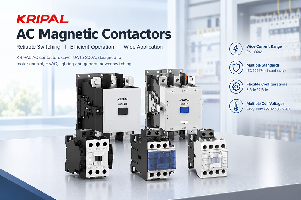
Definite-purpose contactors and IEC contactors are both widely used within equipment assemblies and control panels. However, their rating formats and application specifications are not directly comparable. A matching headline ampere rating alone does not guarantee two contactor devices are interchangeable.
This blog explains how to evaluate these two contactor types based on load duty cycle, published electrical ratings, coil specifications, mounting constraints, and real-world application requirements. It also delivers a practical checklist for equipment builders when selecting or replacing contactors. Always cross-reference all critical parameters against the latest manufacturer datasheet and relevant certification documents.
Where the Two Approaches Differ
Both contactor families rely on electromagnetic actuation to switch electrical loads. The core difference for engineering selection lies in rating methodology, published application data, and suitability for actual operating duty cycles.
Scope of Each Standard
IEC contactors are specified against established product standards, utilization categories, and rated operational values. IEC 60947-4-1 is the primary global standard for low-voltage contactors and motor starters.
Definite-purpose contactors originate primarily from the North American HVAC/R market and are commonly qualified to UL 508 and ARI 780, rated for narrow, predefined target applications. Valid ratings, test conditions, and approvals vary per individual product and sales territory. Never assume all products within either group follow identical qualification workflows.
In practical engineering work, always compare parameters under equivalent load duty conditions. Panel designers often depend on utilization-category ratings, while OEM equipment builders frequently work with application-specific published ratings. Neither design type is universally superior. Suitability is fully determined by your field application and verified product documentation.
How Ratings Are Published
Contactor datasheets list distinct current values for different load duties. For IEC-style contactors, rated operational current (Ie) must always be interpreted together with operational voltage, utilization category, and stated test conditions. Conventional free-air thermal current (Ith) represents thermal withstand capability under lab conditions and cannot be treated as equivalent to operational-current ratings.
For instance, a current rating valid for resistive or mildly inductive loads cannot automatically apply to motor-switching scenarios. Similarly, two contactors printed with the same ampere value can diverge greatly in permissible duty cycles, electrical endurance, coil requirements, and certification status. Always perform like-for-like rating comparison rather than relying purely on headline current numbers.
Comparing the Published Figures
Start your comparison by documenting real-world load characteristics and operating conditions, then locate ratings corresponding to that exact duty. Confirm operating voltage, load type, start-stop profiles, switching frequency, coil supply, and mandatory approvals before comparing frame size or unit price.
Frames and Current Ranges
KRIPAL manufactures AC magnetic contactors covering 9 A up to 800 A for motor control, HVAC systems, lighting circuits, and general-purpose power switching. Relevant product families include UKC1, UKC2, and UKC5. The UKC1 series carries UL Listing certification. Models are available in 3-pole and 4-pole configurations, with AC coil voltage options: 24 V, 110 V, 220 V, and 380 V. Not every voltage/pole combination exists across every series. Confirm exact ratings, pole count, and coil specifications in the latest datasheet before finalizing your bill-of-materials.
Definite-purpose contactors publish ratings tied to specific end-use loads. You must map these application-based ratings to the equivalent working duty of alternate contactor solutions; ampere value alone cannot prove functional equivalence.
Utilization Categories
Utilization categories define validated switching duties for contactors. AC-1 applies to non-inductive or slightly inductive resistive loads. AC-3 covers starting squirrel-cage induction motors and switching off motors at running speed. Final selection must comply with applicable standards and manufacturer datasheets.
Many definite-purpose contactors provide application-level performance data instead of standardized utilization-category tables. In these cases, follow the official published application limits and certifications; do not infer wider or narrower performance without supporting documentation.
| Comparison point | IEC contactor (typical selection approach) | Definite purpose contactor (typical selection approach) |
| Basis of selection | Applicable standard, utilization category, and rated operational values | Specified application and manufacturer-published ratings/approvals |
| Current ratings | Separate ratings defined by duty, voltage, and utilization category | Ratings tied to defined equipment or load type |
| Motor or demanding duty | Reference utilization category plus model-specific performance data | Confirm published application rating explicitly covers your operating duty |
| Replacement decision | Validate electrical, mechanical, and compliance requirements | Validate electrical, mechanical, and compliance requirements |
| Best fit | Depends on project specifications and documented performance | Depends on equipment application and documented performance |
Physical Differences
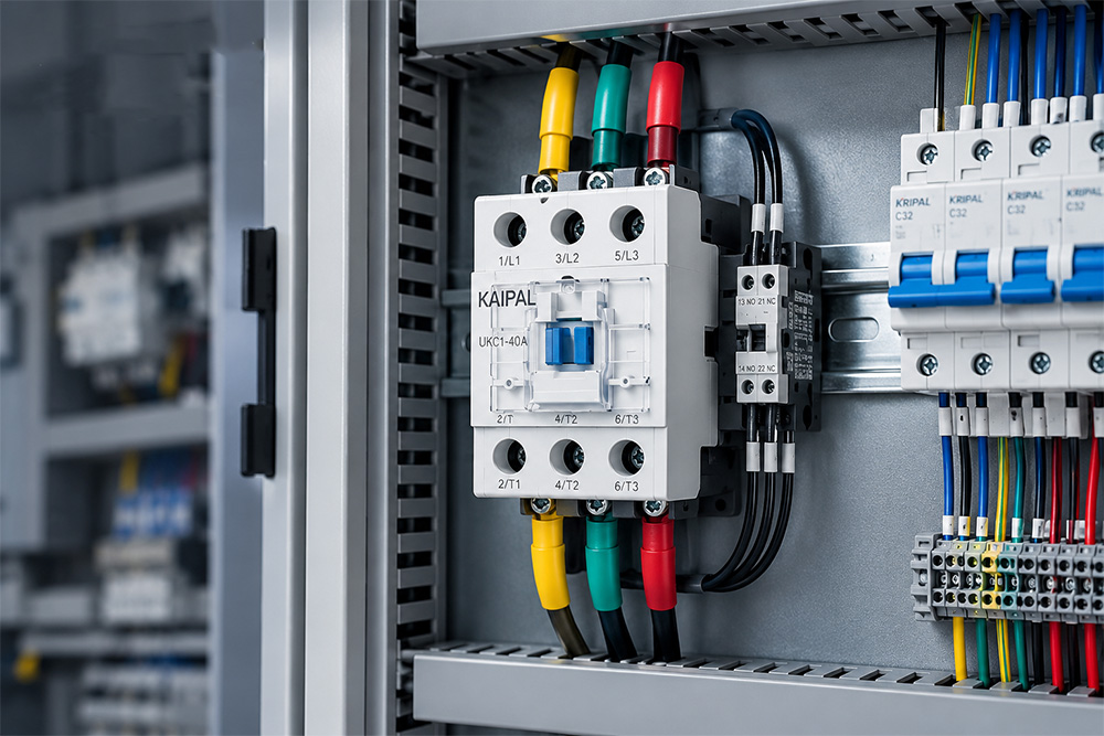
Physical footprint and terminal layouts differ per individual model and cannot be judged solely by contactor product family. Before specifying a drop-in replacement, cross-check dimensional drawings, mounting style, terminal layout, minimum clearance distances, and field-wiring accessibility.
Mounting and Dimensions
Some contactors support DIN-rail mounting; others use panel-mount brackets or custom footprints. These are common design patterns and are not exclusive rules for IEC or definite-purpose families. Mounting compatibility must be verified against manufacturer dimension drawings before substitution.
Enclosure depth and clearance margins become critical inside compact electrical cabinets. Confirm available cabinet space, tool access for conductors, ventilation requirements, and safety clearances. Even a contactor meeting all electrical requirements may be unusable if it cannot physically fit or be safely wired within the assembly.
Terminals and Wiring Space
Terminal construction, compatible conductor cross-section, and tightening torque requirements vary model-to-model. Review datasheet information for wire gauge range, terminal torque values, wire type, and restrictions regarding wire ferrules or accessories. Do not assume factory-wired suitability equals field-wiring suitability (or vice-versa) without reading official manufacturer instructions.
Where Each Type Fits
Correct component selection is driven by load profile, equipment mechanical design, and manufacturer published documentation. Base decisions on documented duty-cycle and installation requirements — not product labeling or ampere rating alone.
Equipment With Fixed Load Profiles
Definite-purpose contactors are well-suited for high-volume manufactured equipment with stable, well-defined loads such as compressors, heating elements, or fans — provided published ratings and certifications fully match application conditions. Whenever load characteristics, control logic, or operating cycles change during product revisions, re-evaluate contactor selection rather than reusing legacy component choices automatically.
Specification-Driven Control Panels
For control panels built against formal project specifications, IEC-compliant contactors with clear utilization-category ratings simplify matching components to diverse loads and working conditions. Selected devices must still satisfy all project-level electrical, mechanical, environmental, and compliance constraints.
KRIPAL AC magnetic contactors comply with IEC 60947-4-1 and hold CE, CB, CCC, UL, and RoHS certifications. Manufacturing runs under an ISO 9001 quality-management system.
Note: ISO 9001 certifies production-process quality and is not a product-level certification. Always validate certification status against model-specific datasheets.
Substituting Between the Two Contact Types
Component substitution may be considered for obsolete, discontinued, or redesigned equipment projects. You cannot safely make swap decisions based purely on product family name, outer physical appearance, or nominal ampere rating. Any proposed replacement must be fully validated against original application constraints and full system-level requirements of your equipment or control panel.
Pre-Substitution Checklist
Applications Requiring Extra Engineering Review
Do not assume either contactor type supports reversing, plug-braking, extremely frequent starting, or other severe switching duties unless manufacturer datasheets explicitly validate these operating modes. If your load falls outside published performance limits, consult the component manufacturer or qualified electrical engineer before performing any substitution.
Common Specification Errors
Frequently Asked Questions
What is the main difference between a definite-purpose contactor and an IEC contactor?
They use different frameworks for publishing application-relevant performance data. IEC-compliant contactors rely on standardized utilization categories and rated operational values. Definite-purpose contactors publish performance figures for specific end-use applications. Always compare official datasheets and certification documents side-by-side.
Can an IEC contactor replace a definite-purpose contactor?
It may be feasible, but only after confirming the IEC contactor is fully rated for your actual load duty and satisfies mechanical, control-circuit, and certification requirements. Similar ampere ratings alone are insufficient justification for replacement.
What do AC-1 and AC-3 mean for contactor selection?
AC-1 and AC-3 are standardized utilization categories describing switching duties. AC-1 applies for non-inductive or slightly inductive loads. AC-3 is used for starting squirrel-cage motors and switching motors at running speed. Refer to your product datasheet for exact application boundaries.
Which ratings must I verify before replacing a contactor?
Confirm load & operational voltage, duty-specific operational current, start-stop behavior, switching frequency, coil supply, pole count, auxiliary contacts, mounting dimensions, terminal limits, and required certifications. Also check compatibility with full-assembly certification constraints.
Why do coil voltage and auxiliary contacts deserve close attention?
The contactor coil must match your control-supply voltage and electrical characteristics. Auxiliary contacts must align with your control-circuit logic and required contact form. Both parameters vary even within a single product family; always check against your exact part-number datasheet.
Comparing the Two Contact Types: Final Workflow
View KRIPAL AC Magnetic Contactor Product Line
|
Download Datasheets
For technical support with contactor selection, share your load type, operating voltage, motor starting method, switching frequency, and control‑coil specifications via our Contact Us page. If available, attach your existing contactor part number or nameplate photograph. Our technical team will review suitable configuration options for your project.
Related Resources
Explore Knowledge Center >

Need a matching KRIPAL product?
Share voltage, quantity and destination. An engineer will reply with options and lead time.
