



Knowledge Center
How to Read Contactor Symbols and Circuit Diagrams
Learn how to read contactor symbols, trace control circuits, and understand A1, A2, and auxiliary terminal numbers like 13-14 and 21-22 in our expert guide.
 August 07, 2026
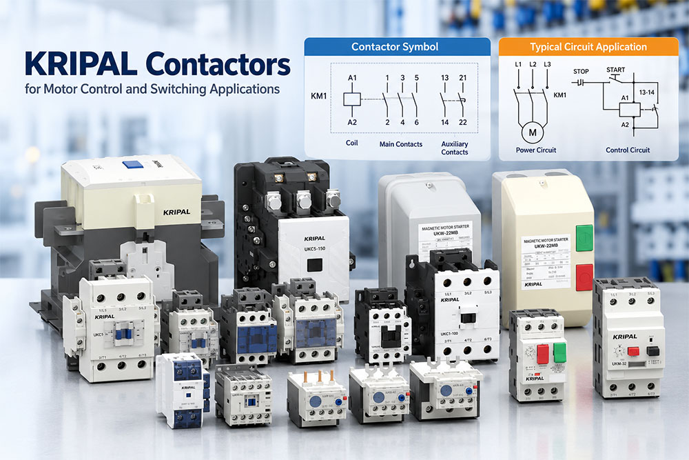
A contactor symbol on a circuit diagram may look complicated at first, but its basic structure is straightforward once you understand the coil, main contacts, and auxiliary contacts. These elements are usually drawn separately even though they belong to the same physical contactor.
This guide explains how to read common contactor symbols, understand terminal numbers such as A1, A2, 1-2, 13-14, and 21-22, and trace a basic control circuit. It also covers start-stop circuits, electrical interlocking, and the difference between power and control circuits.
KRIPAL manufactures UKC contactors for low-voltage switching and control applications. The examples below focus on common IEC-style contactor markings, but the terminal markings and circuit arrangement should always be verified against the specific contactor and its technical documentation.
The Three Parts of a Contactor Symbol
A conventional contactor is normally represented by three related elements on a circuit diagram: the coil, the main contacts, and the auxiliary contacts. The coil is usually shown in the control circuit and is identified by terminals A1 and A2. When the correct control voltage is applied to the coil, the contactor operates. The main contacts are shown in the power circuit. On a typical three-pole contactor, they are commonly identified as 1-2, 3-4, and 5-6. The auxiliary contacts are used in control, signaling, interlocking, and holding circuits. Common markings include 13-14 for a normally open (NO) auxiliary contact and 21-22 for a normally closed (NC) auxiliary contact.
The coil and contacts are connected conceptually by a common device designation, such as KM1. This means that the coil, main contacts, and auxiliary contacts identified as KM1 belong to the same physical contactor. The designation, rather than their physical position on the drawing, allows you to recognize the components as one device.
The Coil Symbol
The coil is the operating element of the contactor. It is commonly marked A1 and A2 and is connected to the control circuit. When the coil is energized with its specified control voltage, the contactor changes the state of its associated contacts. Normally open contacts close, while normally closed contacts open.
The coil voltage may be indicated directly on the diagram or on the contactor, such as 24 V DC, 110 V AC, or 230 V AC. The actual control voltage must match the rating specified for the particular contactor coil.
This is important when reading a circuit diagram: the voltage of the main power circuit and the voltage of the contactor coil are not necessarily the same. A motor may be supplied by a three-phase power circuit while the contactor coil is operated by a lower control voltage.
The Contact Symbols
Contact symbols are normally represented in their normal or rest state, meaning the contactor coil is de-energized unless the diagram specifies another condition. A normally open (NO) contact is shown open in its normal state. When the associated contactor operates, the NO contact closes. A normally closed (NC) contact is shown closed in its normal state. When the associated contactor operates, the NC contact opens. For example, a 13-14 auxiliary contact is commonly used as an NO contact, while 21-22 is commonly used as an NC contact. The important point is to identify the contact’s normal state and then determine how that state changes when the associated coil is energized.
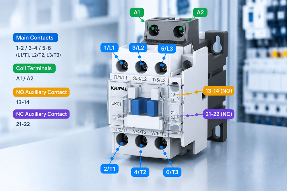
A contactor symbol becomes easier to understand when you compare it with the actual device. The example above shows how common terminal markings on a KRIPAL UKC1 contactor correspond to the coil, main contacts, and auxiliary contacts used in control diagrams.
The terminal markings shown above follow common IEC-style identification practices. Always verify the exact terminal arrangement using the product datasheet before wiring.
Understanding Contactor Terminal Numbers
Terminal numbers provide a quick way to identify the function of contacts, but numbering conventions should be treated as typical IEC-style markings rather than an absolute rule for every device. Always check the terminal markings and wiring diagram supplied with the specific contactor.
Main Contact Numbers
For many IEC-style contactors, the main poles are identified as:
| Pole | Common terminals | Typical function |
| 1st pole | 1-2 | L1 / T1 |
| 2nd pole | 3-4 | L2 / T2 |
| 3rd pole | 5-6 | L3 / T3 |
The odd-numbered terminals are commonly used on the supply side, while the even-numbered terminals are commonly used on the load side.
For example:
1/L1 → 2/T1
3/L2 → 4/T2
5/L3 → 6/T3
A three-pole contactor therefore provides three main switching paths. However, the actual connection should always follow the markings on the specific device.
Auxiliary Contact Numbers
Auxiliary contacts use two-digit terminal numbers to identify their function in a control circuit. Unlike the main power contacts, auxiliary contacts usually carry only control signals rather than the main load current.
In common IEC-style contactor markings, the most frequently used auxiliary contact numbers are:
| Terminal marking | Contact type | Contact state (coil de-energized) | Typical application |
| 13-14 | Normally Open (NO) | Open when the contactor is OFF; closes when energized | Self-holding circuits, status feedback, control signals |
| 21-22 | Normally Closed (NC) | Closed when the contactor is OFF; opens when energized | Electrical interlocking, safety-related control functions |
| 31-32 | Normally Closed (NC) | Closed when the contactor is OFF; opens when energized | Additional control or signaling circuits |
| 33-34 | Normally Open (NO) | Open when the contactor is OFF; closes when energized | Additional control or signaling circuits |
For example, when a contactor marked KM1 energizes:
- Its 13-14 auxiliary contact closes, allowing it to maintain the control circuit in a self-holding application.
- Its 21-22 auxiliary contact opens, which can prevent another contactor from operating in an electrical interlock circuit.
These terminal markings are widely used in IEC-style industrial control equipment. However, the exact auxiliary contact arrangement depends on the contactor design and attached auxiliary modules, so the manufacturer’s wiring diagram should always be checked before installation.
How to Trace a Contactor Control Circuit
The easiest way to understand a control circuit is to follow the current path from the control supply toward the contactor coil. Consider a standard start-stop circuit. The control supply passes through a STOP push button, normally closed, and then through a START push button, normally open, before reaching the contactor coil. The contactor’s own 13-14 NO auxiliary contact is normally connected in parallel with the START button.
When the START button is pressed, current flows through the closed STOP contact and the START contact to energize the coil. The contactor then closes its 13-14 auxiliary contact. Because 13-14 is connected in parallel with the START button, it provides an alternative current path. When the START button is released, the auxiliary contact keeps the coil energized. This is commonly called a self-holding, sealing, or holding circuit.
When the STOP button is pressed, its NC contact opens. The coil circuit is interrupted, the contactor drops out, and the 13-14 auxiliary contact returns to its normal open state.
This simple sequence is one of the most useful patterns to recognize when reading contactor control diagrams.
Reading Electrical Interlocking
Electrical interlocking is commonly used in circuits where two contactors must not be energized at the same time, such as motor reversing circuits. For example, a reversing circuit may use two contactors:
- KM1 for forward operation
- KM2 for reverse operation
The NC auxiliary contact of KM2 can be connected in series with the KM1 coil, while the NC auxiliary contact of KM1 is connected in series with the KM2 coil. The basic logic is:
KM1 coil → KM2 NC auxiliary contact
KM2 coil → KM1 NC auxiliary contact
When KM1 energizes, its NC auxiliary contact opens. This prevents the KM2 coil from being energized through the control circuit. Likewise, when KM2 energizes, its NC auxiliary contact opens and prevents KM1 from energizing. In practical reversing starters, electrical interlocking is commonly combined with mechanical interlocking to provide an additional means of preventing both contactors from closing simultaneously.
Common Symbols You Will Meet
A contactor diagram normally includes more than the contactor itself. Understanding the other symbols makes the complete circuit easier to follow.
These symbols are commonly encountered in motor control circuits. Their exact representation may vary depending on the drawing convention, so always refer to the circuit documentation for the specific application.
| Component | Typical role in the diagram |
| Motor | Three-phase load, commonly connected through U, V, and W terminals |
| Contactor | Switches the motor power circuit |
| Overload relay | Provides motor overload protection and a control trip signal |
| Overload NC contact | Commonly identified as 95-96 |
| Fuse or circuit breaker | Provides short-circuit and/or overcurrent protection according to the circuit design |
| STOP push button | Normally closed control device |
| START push button | Normally open control device |
The overload relay’s 95-96 NC contact is commonly incorporated into the contactor control circuit. If the overload relay trips, this contact opens and interrupts the contactor coil circuit.
A typical motor starter control path may therefore look like:
Control supply → STOP NC → overload 95-96 → START NO → contactor coil A1/A2
The exact circuit depends on the application and control architecture.
The Power Circuit vs. the Control Circuit
One of the most important distinctions when reading a contactor diagram is the difference between the power circuit and the control circuit. The power circuit carries the load current. In a motor starter, it normally contains the supply conductors, contactor main contacts, overload protection, and motor. The control circuit operates the contactor. It may contain the control power supply, STOP and START push buttons, auxiliary contacts, overload relay contacts, interlocking contacts, and the contactor coil. The two circuits may operate at different voltages. For example, a three-phase motor may use a higher power-circuit voltage while the contactor coil operates from a separate control voltage. When troubleshooting, always identify which circuit you are working on and follow the manufacturer’s safety and isolation procedures.
Frequently Asked Questions
What does KM1 mean on a circuit diagram?
KM1 is a device designation commonly used to identify the first contactor in a control circuit. The coil, main contacts, and auxiliary contacts carrying the same designation belong to the same physical device.
What do 13-14 mean on a contactor?
13-14 commonly identifies a normally open auxiliary contact. When the associated contactor operates, the contact closes and can be used for self-holding, signaling, or other control functions.
What do 21-22 mean on a contactor?
21-22 commonly identifies a normally closed auxiliary contact. It is frequently used for electrical interlocking or other control functions where the contact needs to open when the associated contactor energizes.
How do I tell a main contact from an auxiliary contact?
Typical main contacts use markings such as 1-2, 3-4, and 5-6, while auxiliary contacts commonly use two-digit markings such as 13-14 and 21-22. Always confirm the markings on the specific contactor.
What is the normal state of a contactor diagram?
The normal state generally represents the condition with the contactor coil de-energized, unless the drawing specifies otherwise. NO contacts are normally shown open and NC contacts normally shown closed.
How do I know the contactor coil voltage?
Look for the coil voltage marking on the circuit diagram, product label, or technical documentation. Typical examples include 24 V DC and 230 V AC. The control supply must match the specified coil rating.
The Pattern Behind Contactor Diagrams
Most conventional contactor diagrams become much easier to understand once you recognize three basic elements: the coil, the main contacts, and the auxiliary contacts. Terminal markings such as A1/A2, 1-2, 3-4, 5-6, 13-14, and 21-22 provide additional clues about the function of each connection. Start-stop circuits and electrical interlocking then show how these contacts work together to control a load.
KRIPAL’s UKC contactor range is designed for low-voltage switching and control applications and uses conventional terminal identification to help users connect and troubleshoot control circuits.
Need help selecting a contactor for your application or understanding a contactor circuit? Explore the KRIPAL UKC contactor range or contact the KRIPAL engineering team with your circuit diagram and application requirements.
Related Resources
Explore Knowledge Center >
Need a matching KRIPAL product?
Share voltage, quantity and destination. An engineer will reply with options and lead time.
