A high-voltage DC contactor is a key switching component in electric vehicles, charging equipment, and other high-voltage DC power systems. It has to carry high current, switch DC loads without a natural current zero-crossing, and maintain reliable contact performance over repeated operations. Selecting a DC contactor is not simply a scaled-up version of AC contactor selection; the arc behavior, coil control, insulation requirements, and environmental protection are different.
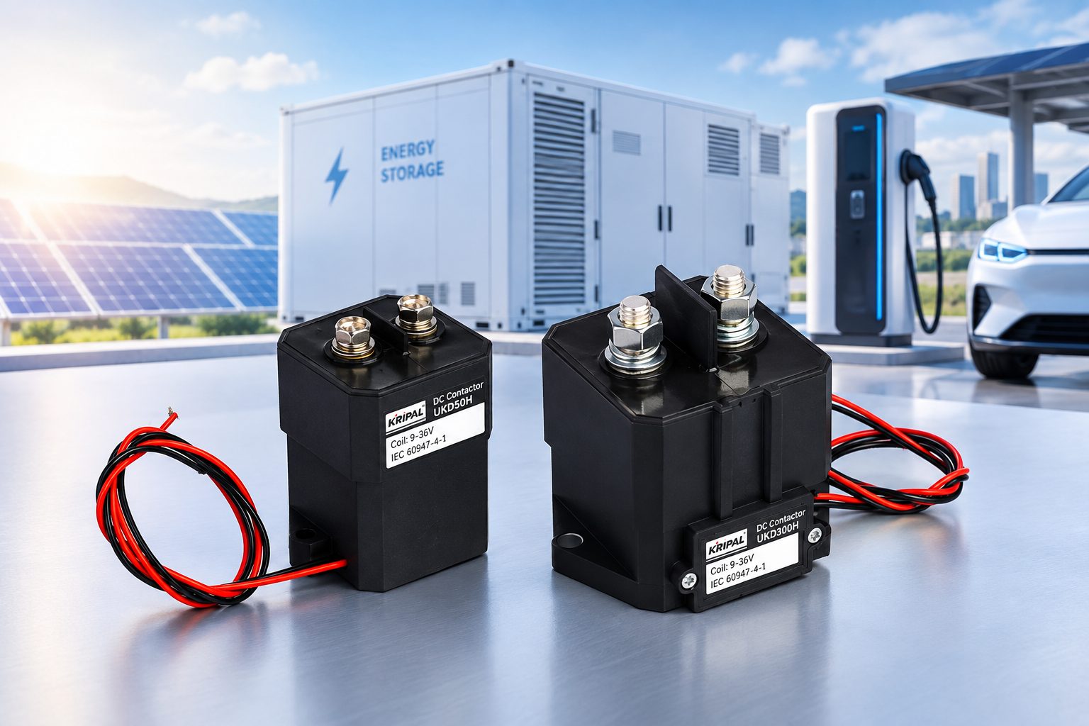
KRIPAL’s UKD-H series is a fully sealed high-voltage DC contactor designed for power switching control in critical DC systems. The series includes 50A, 100A, 150A, 200A, 250A, and 300A models, with contact ratings up to 750V DC depending on the model. This guide explains the key parameters to check when selecting a high-voltage DC contactor.
Why High-Voltage DC Contactors Are Different
DC Arc Behavior
The main difference is the DC arc. When an AC contactor opens, the alternating current naturally passes through zero during each cycle, which helps the arc extinguish. A DC contactor does not have this natural current zero-crossing, so the arc must be controlled by the contactor’s internal arc-quenching design.
Voltage and Insulation
The second difference is the voltage level. High-voltage DC systems can operate at several hundred volts, so the contactor must be designed for the applicable DC voltage and insulation requirements. The contact gap, insulation system, and sealed contact chamber all contribute to reliable switching and isolation.
| Characteristic |
AC Contactor |
High-Voltage DC Contactor |
| Current zero-crossing |
Current naturally passes through zero during each AC cycle |
No natural current zero-crossing |
| Arc behavior on opening |
The zero-crossing helps extinguish the arc |
The DC arc must be controlled by the contactor’s arc-quenching design |
| Voltage requirement |
Depends on the AC system voltage |
Must be selected according to the applicable DC operating voltage and contactor rating |
| Contact chamber |
May use an open or enclosed structure depending on the application |
High-voltage designs may use a sealed chamber to control the switching environment |
The Sealed Contact Advantage
High-voltage DC contactors used in demanding applications can use sealed contact chambers to protect the contacts from moisture and contamination and to provide a controlled internal environment for DC switching.
The KRIPAL UKD-H series uses high-strength epoxy resin sealing and a nitrogen-based gas filling. According to the product specifications, the contact area has an IP67 protection grade, while controlled internal atmosphere helps reduce contamination and oxidation and supports stable switching performance.
The UKD-H series also uses a dual-coil design with an energy-saving PCB. This makes the coil specification an important part of the selection process, particularly when the contactor is controlled by a battery management system or other DC control circuit.
The Coil Power Difference
The coil control circuit is another important selection parameter. UKD-H contactors use DC coils, but the available coil specifications differ by model.
The UKD-50H is specified with a 9–36V DC coil, while the UKD-100H, UKD-150H, UKD-200H, UKD-250H, and UKD-300H specifications list 12V, 24V, and other applicable coil options. The exact coil voltage must therefore be selected according to the individual model and control system rather than assuming that every UKD-H contactor uses the same coil range.
The coil’s pickup voltage, release voltage, pickup time, release time, starting current, and standby power should also be considered. For example, the UKD-100H–UKD-300H specifications list a maximum starting current of 2.5A and standby power of no more than 4.0W.
The Applications
High-voltage DC contactors are used in several types of DC power systems. Their required current, voltage, switching frequency, and electrical life depend on their position in the circuit.
Electric Vehicles
An EV can use several high-voltage contactors for different switching functions, including:
- Main battery connection and isolation
- Pre-charge circuits
- Charging circuits
- Auxiliary high-voltage loads
The contactor must be selected according to the current and voltage of its specific circuit. A main contactor and a pre-charge contactor do not necessarily have the same electrical duty.
The KRIPAL UKD-H series is specified for electric buses and electric vehicles. The product range covers 50A to 300A models, with the individual contact rating depending on the model.
Battery and DC Power Systems
High-voltage DC contactors can also be used to control battery and other DC power circuits. The contactor must carry the required continuous current and withstand the electrical and environmental conditions of the installation.
However, the contactor’s switching rating should not be confused with the short-circuit rating of the complete DC power system. Where high fault currents are possible, the contactor must be coordinated with the system’s dedicated overcurrent or short-circuit protection, such as a DC MCCB or other protection devices, and may also work with a DC isolator for maintenance isolation.
EV Charging Stations
The UKD-H series is also specified for EV charging piles and stations. In this application, the contactor selection depends on the DC voltage, charging current, switching frequency, and required electrical life.
The product specifications also identify automotive air-conditioning systems and telecom power supplies as application areas.
The Selection Process
A high-voltage DC contactor should be selected by checking several key data points on the manufacturer’s datasheet:
| Step |
What to check |
Why it matters |
| 1. Continuous current |
Rated contact current under the specified conditions |
Determines whether the contactor can carry the required load continuously |
| 2. DC voltage |
Contact rated voltage and actual system voltage |
Determines whether the contactor is suitable for the DC circuit |
| 3. Switching and breaking capability |
Specified electrical switching and maximum breaking performance |
Determines whether the contactor can perform the required switching duty |
| 4. Coil control |
Coil voltage, starting current, and standby power |
Ensures compatibility with the control circuit |
| 5. Electrical and mechanical life |
Life at the specified current and voltage |
Determines expected switching endurance |
| 6. Environment |
Temperature, vibration, impact, sealing, and installation conditions |
Determines whether the contactor can operate reliably in the actual environment |
1
Step 1: The Continuous Current
The contactor’s rated contact current must be suitable for the maximum continuous current of the circuit under the manufacturer’s specified conditions.
The KRIPAL UKD-H range includes:
UKD-50H — 50A
UKD-100H — 100A
UKD-150H — 150A
UKD-200H — 200A
UKD-250H — 250A
UKD-300H — 300A
The product specifications state a continuous working duty, with the terminal temperature rise limited to no more than 65K. The specified operating temperature range is -40°C to +85°C.
The correct model should therefore be selected according to the actual circuit current and the conditions stated in the applicable product specification.
2
Step 2: The DC System Voltage
The contact rated voltage is a critical parameter and must not be inferred simply from the nominal voltage of the application.
For the UKD-H series, the contact rated voltage is specified as:
- UKD-50H: 750V DC, 50A
- UKD-100H: 750V DC, 100A
- UKD-150H: 750V DC, 150A
- UKD-200H: 750V DC, 200A
- UKD-250H: 750V DC, 250A
- UKD-300H: 750V DC, 300A
This means the original statement that an “800V system needs a 900V or 1000V contactor” should not be used as a general rule for the UKD-H series. The actual system voltage must be checked against the rated voltage of the specific contactor.
For systems operating above the contactor’s rated voltage, a different contactor configuration with a suitable DC voltage rating should be selected.
3
Step 3: Switching and Breaking Capability
A high-voltage DC contactor’s switching capability must be evaluated according to the actual voltage, current, load and switching duty.
The UKD-H datasheets specify maximum breaking current separately from the continuous contact rating. For example, the UKD-50H specifies a maximum breaking current of 500A at 320V DC for one operation, while the UKD-100H through UKD-300H specifications list 2000A at 320V DC for one operation.
These values should not be interpreted as the contactor’s continuous current or as a general short-circuit interruption rating for the complete system. Short-circuit protection and contactor selection must be coordinated according to the actual circuit architecture and protection device.
The instantaneous maximum current is also model-dependent: the UKD-50H is specified at 350A for no more than 1 second; UKD-100H is specified at 500A for no more than 1 second; and UKD-150H through UKD-300H are specified at 800A for no more than 1 second.
4
Step 4: The Coil Control
The coil voltage and power must match the control circuit.
For the UKD-H series, the coil specification is model-dependent. The UKD-50H supports a 9–36V DC coil specification, while the higher-current models list 12V, 24V, and other coil options.
The control system should therefore be matched to the exact coil specification of the selected model. The starting current and standby power should also be checked when sizing the driver or control output.
The UKD-H series uses a dual-coil design with an energy-saving PCB, and the product specifications include a pickup time of no more than 30ms and a release time of no more than 20ms.
5
Step 5: The Life Rating
Electrical and mechanical life must be evaluated together with the actual switching conditions.
The UKD-H series specifies a mechanical life of at least 300,000 operations. Electrical life varies according to the model and load condition.
For example, the UKD-150H is rated for at least 1,000 electrical operations at 1000V/70A, 900V/90A, and 750V/150A, while at 450V/150A the specified electrical life increases to at least 5,000 operations. The UKD-300H similarly specifies different electrical life values for different voltage/current combinations.
This illustrates why electrical life should never be represented by a single number without stating the corresponding voltage and current conditions.
6
Step 6: The Environment
The operating environment is another important selection factor.
The UKD-H series specifies:
- Working temperature: -40°C to +85°C
- Vibration: sine shock, 2.5g, 5–50Hz
- Impact: 50g, 11ms, half sine
- Mounting altitude: up to 2km
- Contact-area protection: IP67
- Continuous working duty
These specifications make the environmental conditions an important part of the selection process, particularly in vehicles and other applications exposed to vibration, temperature cycling, moisture, or mechanical impact.
The Pre-Charge Circuit
The pre-charge circuit is an important part of many high-voltage DC system designs. When a main contactor closes onto a discharged DC-link capacitor, the initial inrush current can be very high.
A pre-charge contactor and resistor can be used to limit this inrush current and allow the DC-link voltage to rise before the main contactor closes.
The pre-charge contactor should be selected according to the actual pre-charge current, voltage, pulse duration, switching frequency, and required electrical life.
Why the Pre-Charge Matters
Without an appropriate pre-charge sequence, a discharged DC-link capacitor can draw a large inrush current when connected directly to the battery or DC source. This can create significant electrical stress on the main contactor and other components in the DC power path and may increase the risk of contact damage or welding.
The pre-charge circuit therefore needs to be considered as part of the overall contactor and DC power-path design.
The Resistor Sizing
The pre-charge resistor is commonly selected according to the DC-link capacitance, desired charging time, allowable initial current, and resistor pulse-energy capability.
For a simplified RC charging circuit:
V(t) = VDC × (1 − e^(-t/RC))
The resistor value affects both the initial current and the charging time. The resistor must also be capable of handling the energy generated during the pre-charge pulse.
The pre-charge contactor must then be checked against the resulting voltage, current, pulse duration, switching frequency, and electrical life.
FAQ
What is the difference between a high-voltage DC contactor and a normal contactor?
A high-voltage DC contactor is specifically designed for DC power switching, where there is no natural current zero-crossing. Its contact system and arc-quenching design must therefore be suitable for the applicable DC voltage and current.
What voltage rating do I need for an EV DC system?
The contactor’s rated DC voltage must cover the actual maximum operating voltage of the circuit. Do not select a contactor simply from the nominal system label; check the manufacturer’s rated contact voltage and the actual operating conditions.
How do I choose the pre-charge contactor?
Start with the DC-link capacitance, target charging time, allowable inrush current, and pre-charge resistor. Then select a contactor whose voltage, current, switching frequency, and electrical life are suitable for the resulting pre-charge duty.
Why are high-voltage DC contactors sealed?
A sealed contact chamber helps protect the contacts from moisture and contamination and provides a controlled internal environment for DC switching. The KRIPAL UKD-H series uses epoxy resin sealing and nitrogen-based gas filling, with an IP67 protection grade for the contact area.
Can I use any coil voltage with a high-voltage DC contactor?
No. The coil voltage must match the specification of the selected contactor. For example, the UKD-50H is specified with a 9–36V DC coil, while other UKD-H models list 12V, 24V, and other applicable coil options. Always check the exact model specification before connecting the control circuit.
What happens if the contactor is undersized?
An undersized contactor can experience excessive contact temperature rise, accelerated contact wear, and damage during high-current switching. Selecting the correct current, voltage, switching capability, electrical life, and environmental rating is therefore essential.
The Six-Data-Point Selection
A high-voltage DC contactor should be selected by checking six main areas: continuous current, DC voltage, switching and breaking capability, coil control, electrical and mechanical life, and environmental conditions.
For the KRIPAL UKD-H series, the product range covers 50A to 300A contact ratings, with contact rated voltage up to 750V DC depending on the model. The series uses sealed construction, nitrogen-based gas filling, a dual-coil energy-saving PCB, and an IP67 contact-area protection grade. Individual models have different coil, electrical-life, instantaneous-current, and breaking-current specifications, so the exact model should always be selected from its applicable datasheet.
For EVs, EV charging equipment, automotive air-conditioning systems, telecom power supplies, and other DC power switching applications, send KRIPAL your circuit voltage, continuous current, switching duty, coil supply, and environmental requirements. Our engineering team can help confirm the appropriate UKD-H configuration. Browse the high-voltage DC contactor range, related contactors and relays, or contact us for application support.
Request a Quote
Technical Reference
Technical data in this article is based on KRIPAL UKD-H series product specifications. Actual contactor selection should be verified against the latest model-specific datasheet and the electrical and environmental conditions of the application.



 Search
 July 30, 2026