


 Search
Knowledge Center
Auxiliary Contact Blocks: Types, Functions and Wiring Guide
Compare front-mount and side-mount auxiliary contact blocks, NO/NC configurations, time-delay options, and wiring best practices for contactor control.
 June 23, 2026
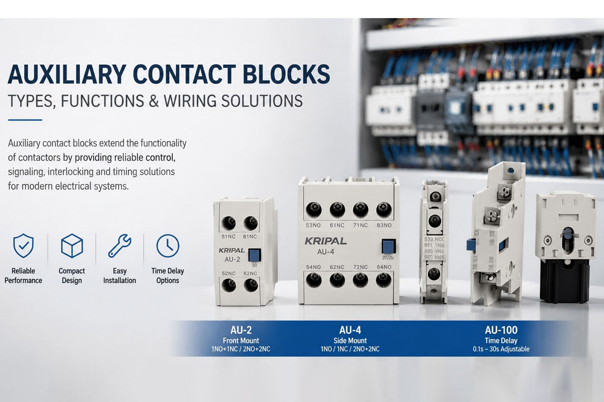
Contactors switch heavy motor and lighting loads, but they rarely communicate their status on their own. An auxiliary contact block fills that gap. It mounts directly onto the contactor body and provides extra low-current contacts for control signaling, status indication, and interlocking logic. For engineers and panel builders, picking the right auxiliary contact block cuts troubleshooting time and prevents control circuit faults before they happen.
How an Auxiliary Contact Block Works
An auxiliary contact block is a snap-on module that mechanically links to the contactor’s moving armature. When the main contacts open or close, the auxiliary contacts follow the same movement. The key difference is that auxiliary contacts are designed for control circuits rather than power switching. Their thermal current rating is typically around 10A, while their utilization current depends on the AC-15 or DC-13 application category. While the main poles handle tens or hundreds of amps.
This separation keeps high-current switching noise away from sensitive PLC inputs and allows the control circuit to confirm the contactor state without tapping the power terminals. The block simply clips onto the front or side of the contactor housing, and a physical linkage pin engages with the contactor armature.
Front Mount vs. Side Mount Auxiliary Contacts
The mounting position of the auxiliary block changes how much panel space you need and how accessible the terminals are during wiring. KRIPAL offers both configurations across the AU series.
Front-mount blocks like the AU-2 sit forward of the contactor, adding depth. This works well when the panel door has clearance and the installer wants terminals facing forward. Side-mount blocks like the AU-4 sit alongside the contactor body and are preferred in shallow enclosures where every millimeter of depth counts.
| Feature | Front Mount (AU-2) | Side Mount (AU-4) |
|---|---|---|
| Panel depth required | More depth behind contactor | Minimal depth, wider footprint |
| Terminal access | Front-facing, easy to reach | Side-facing, requires lateral clearance |
| Typical use | DIN rail with open front access | Compact panels, stacked contactors |
| Contact configuration | 1NO+1NC or 2NO+2NC | Single pole or 2-pole |
Instantaneous vs. Time Delay Auxiliary Contacts
Not all auxiliary contacts switch at the same moment. Standard instantaneous contacts change state as soon as the contactor armature moves. Time-delay auxiliary contacts, available in the AU-100 series, introduce a programmable off-delay or on-delay before switching.
Off-Delay
Keeps the auxiliary circuit closed for a set period after the main contactor drops out. Off-delay auxiliary contacts are commonly used for delayed shutdown sequences, ventilation fans, pump after-run control, and interlocking circuits where a controlled delay is required.
On-Delay
Waits before closing. This is useful for staggered load startups where two motors must not start simultaneously.
No external timer relay is needed, which reduces component count and simplifies panel wiring. Delay ranges are typically adjustable from 0.1 seconds to 30 seconds.
Normally Open (NO) vs. Normally Closed (NC)
Auxiliary contact blocks come in NO (Normally Open), NC (Normally Closed), or mixed configurations. The designation refers to the contact state when the contactor coil is de-energized.
- NO (Normally Open): Closes when the contactor pulls in. This is the standard choice for status feedback (when the contactor is energized, the auxiliary contact can send a status signal to the PLC input).
- NC (Normally Closed): Opens when the contactor pulls in. This is used for safety interlocks and fault signaling (if the contactor drops out unexpectedly, the NC contact closes and triggers an alarm or safety relay).
Having both in one block gives the control circuit a complete status picture. The NO contact confirms the contactor is energized, and the NC contact indicate the contactor is in its normal released position and are often used for interlocking and fault monitoring. If both report the same state, it immediately flags a mechanical fault.
Control Wiring Best Practices
Auxiliary contact wiring carries control signals, not power, so the wire gauge can be smaller (typically 0.75mm² to 1.5mm²).
Isolate your wiring
Route auxiliary wiring separately from power cables. Run control wires in a dedicated duct or use shielded cable when they share a trunk with power conductors. Inductive coupling from a contactor’s main load wires can induce enough voltage on an unshielded auxiliary wire to false-trigger a sensitive PLC input. Control wiring practices should follow IEC 60204-1 requirements for industrial machinery electrical equipment.
Label everything
Label every auxiliary wire at both ends with the contactor designation and contact number. A panel with six identical contactors becomes unserviceable without clear labeling. Mark the wiring diagram reference next to each terminal strip connection.
How to Choose the Right Auxiliary Contact Block
Selecting the correct auxiliary contact block depends on the contactor model, control requirements, installation space, and switching application. Choosing the wrong auxiliary contact configuration may cause wiring problems, incorrect feedback signals, or compatibility issues.
1. Check Contactor Compatibility
The first step is to confirm that the auxiliary contact block matches the contactor series.
Auxiliary contact blocks are designed with specific mechanical mounting structures. A front-mounted block or side-mounted block from one product family may not fit another contactor series.
Before installation, verify:
- Contactor model and frame size
- Mounting position (front or side)
- Number of available mounting locations
- Manufacturer compatibility
For example, KRIPAL AU series auxiliary contact blocks are designed for use with compatible KRIPAL contactors, providing secure mechanical linkage and reliable switching performance.
2. Select the Correct Contact Configuration (NO, NC, or Combination)
The contact arrangement should match the control circuit requirements.
Common configurations include:
1NO (Normally Open) Used for:
- Contactor status feedback
- PLC input signals
- Running indication lamps
The contact closes when the contactor coil is energized.
1NC (Normally Closed) Used for:
- Electrical interlocking
- Fault monitoring
- Safety-related control circuits
The contact opens when the contactor operates.
1NO + 1NC or 2NO + 2NC Used when both status indication and interlocking functions are required in the same control system.
3. Choose the Right Mounting Type
Auxiliary contact blocks are commonly available in front-mount and side-mount designs.
Front Mount Auxiliary Contact Best for:
- Standard control cabinets
- Applications requiring easy terminal access
- Panels with sufficient depth space
Advantages:
- Simple installation
- Clear terminal visibility
- Convenient maintenance
Side Mount Auxiliary Contact
Best for:
- Compact electrical enclosures
- High-density control panels
- Applications where cabinet depth is limited
Advantages:
- Saves panel depth
- Suitable for narrow installations
- Allows flexible panel layout
4. Consider Application Requirements
Different control systems require different auxiliary contact functions.
- For simple status indication: A standard instantaneous auxiliary contact is usually sufficient.
- For applications requiring delayed switching: A time-delay auxiliary contact may be preferred.
Typical applications include:
- Motor control panels
- Pump control systems
- Fan delay circuits
- Sequential machine control
- Electrical interlocking systems
For complex timing functions or longer delay ranges, a separate timer relay may provide greater flexibility.
5. Check Electrical Ratings
Although auxiliary contacts are installed on power contactors, they are designed mainly for control circuits rather than high-power switching.
Before selection, check:
- Rated insulation voltage (Ui)
- Thermal current rating (Ith)
- Utilization category (such as AC-15 or DC-13)
- Control voltage requirements
The auxiliary contact rating must match the actual control load to ensure reliable operation and long service life.
6. Consider Future Expansion Requirements
When designing control panels, consider future expansion requirements. Selecting an auxiliary contact block with additional NO or NC contacts can reduce modification time when new monitoring or interlocking functions are added.
Next Steps
Browse the complete range of KRIPAL Auxiliary Contact Blocks including the AU-2, AU-4, and AU-100 series.
Product examples: AU-2 Front Mount, AU-4, and AU-100 Time Delay.
Need help configuring interlocks for your specific panel build? Contact KRIPAL engineering for technical support and sizing recommendations.
Frequently Asked Questions
Q: Can I add an auxiliary contact block to an existing contactor after installation?
Yes. KRIPAL AU series blocks are designed for simple field installation. Just de-energize the panel, snap the block onto the contactor body, and wire the terminals. No special tools are required beyond a standard screwdriver.
Q: What is the maximum number of auxiliary contact blocks a contactor can accept?
Most UKC series contactors can accommodate up to two side-mount blocks and one front-mount block. However, always verify the specific contactor’s datasheet, as larger frame sizes often support additional blocks.
Q: Do auxiliary contacts share the same voltage rating as the main poles?
The insulation voltage rating is generally the same (690V or 1000V, depending on the series). However, the thermal current (Ith) rating is significantly lower—typically 10A—since auxiliary contacts are designed strictly for control-level currents.
Q: What happens if an auxiliary contact welds shut?
A welded contact fails to change state when the contactor operates, causing a dangerous discrepancy between the physical contactor position and the PLC control signal. Using dual-contact monitoring (wiring both NO and NC contacts) is the best practice to detect and isolate this exact fault.
Q: When should I use a time-delay auxiliary contact instead of a standalone timer relay?
Choose an AU-100 time-delay block to save panel space, reduce component count, and simplify your wiring layout. If your application requires delays longer than 30 seconds or complex, multi-range timing sequences, a separate timer relay is the better choice.
Related Resources
Explore Knowledge Center >

Need a matching KRIPAL product?
Share voltage, quantity and destination. An engineer will reply with options and lead time.
