



Knowledge Center
Contactor Contact Welding: Causes and Prevention
Learn why contactor contacts weld: short-circuit faults, capacitive inrush, coil chatter, and DC arcing. Discover prevention methods and coordination rules.
 August 26, 2026
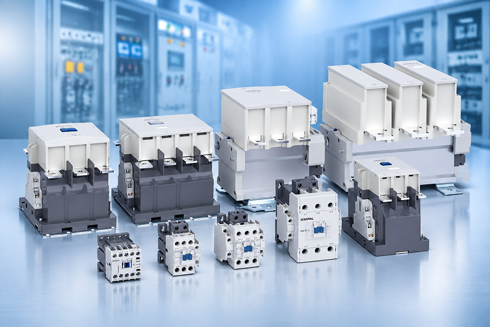
Contactor contact welding is a common failure in industrial electrical systems. It occurs when the main contacts fuse together and cannot separate normally, even after the coil is de-energized. As a result, the connected load may remain energized when the control circuit commands the contactor to open. Contact welding is rarely a random failure. It is usually associated with excessive making current, unsuitable switching conditions, prolonged electrical arcing, unstable coil voltage, or inadequate short-circuit coordination.
Understanding why contactor contacts weld is essential for selecting the correct switching device, improving electrical system reliability, and preventing repeated equipment failures. This guide explains the main causes of contact welding, practical prevention methods, and the considerations involved in AC, DC, and capacitor-switching applications.
How Contact Welding Happens
Contact welding occurs when the electrical and thermal stress at the contact interface becomes high enough to melt the contact material and cause adjacent surfaces to fuse together.
Two mechanisms account for many contact welding incidents: excessive current during closing and prolonged arcing during switching.
Making onto a Fault
When a contactor closes onto an existing short circuit, a very high current can flow through the contacts. The actual current depends on the available fault level and the impedance of the electrical circuit.
During contact closure, mechanical contact bounce can occur. Repeated making and breaking at the contact interface may generate electrical arcs, causing localized heating, pitting, and melting. If the molten contact surfaces remain in contact, they can fuse together as they cool.
A standard contactor is not designed to independently interrupt short-circuit current. Its ability to withstand short-circuit conditions depends on the tested combination with an appropriate short-circuit protective device (SCPD), such as a fuse or circuit breaker.
This is why short-circuit coordination is important. According to IEC 60947-4-1, Type 1 and Type 2 coordination describe different levels of protection between the switching device and its associated short-circuit protective device:
The correct coordination must be verified for the actual fault level and the specified combination of switching device and protective device.
Capacitive Inrush
Switching a capacitor bank can produce a high transient inrush current, particularly when additional capacitor stages are connected to an existing energized bank.
Unlike normal motor starting, capacitor switching involves charging a capacitive load. The initial current depends on the capacitance, residual voltage, supply impedance, transformer characteristics, cable inductance, and switching arrangement.
During back-to-back capacitor switching, the transient current can become particularly high because previously energized capacitor stages exchange energy with the newly connected stage.
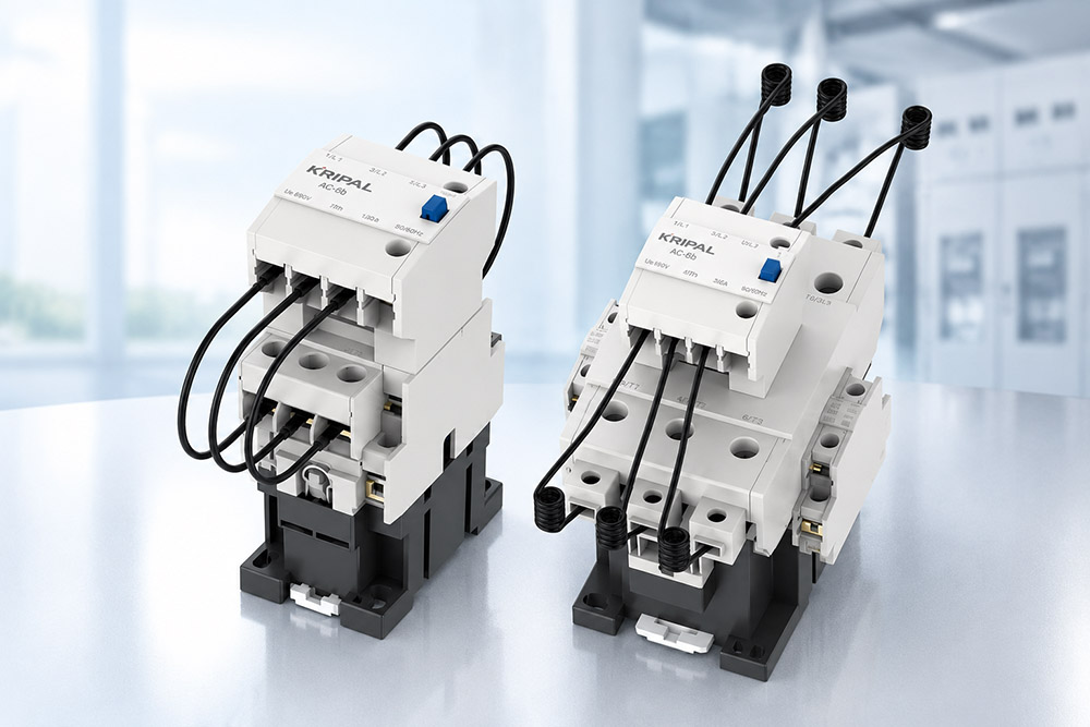
Standard motor-duty contactors should not automatically be assumed suitable for this application. Capacitor banks should be switched using contactors specifically rated for the applicable capacitor-switching duty, typically classified as AC-6b under IEC 60947-4-1.
Capacitor-duty contactors may incorporate pre-insertion contacts and current-limiting resistors to reduce the initial inrush current and protect the main contacts.
The selection of a suitable capacitor-duty contactor should consider the capacitor bank rating, switching frequency, expected inrush current, and the manufacturer’s specified operating conditions.
The Main Causes of Contactor Contact Welding
A contactor that welds during operation within its stated ratings may be experiencing conditions that were not adequately considered during system design or selection.
Several factors can contribute to premature contact failure.
Coil Voltage and Chatter
A contactor that repeatedly opens and closes due to unstable coil voltage is described as chattering.
Each unintended switching operation creates additional electrical arcing at the main contacts. Repeated contact bounce and arcing can accelerate contact erosion, increase localized heating, and eventually cause contact welding.
Common causes include:
Coil voltage should be measured directly at the coil terminals during both pick-up and steady-state operation.
For DC coils fitted with a freewheel diode, the diode can slow the decay of the magnetic field and increase the contactor’s release time. The suppression circuit should therefore be considered when designing the control system.
Arc Duration at DC
DC switching presents different challenges from AC switching. In an AC circuit, the current naturally passes through zero during every cycle, helping the arc extinguish. In a DC circuit, there is no natural periodic current zero, so the switching device must control and extinguish the arc through its designed arc-management system.
DC contactors may use magnetic blowout arrangements and arc chambers to stretch, cool, and extinguish the arc. A contactor rated for AC operation cannot automatically be used in a DC circuit. Its contact spacing, arc chamber, and extinguishing characteristics may not be suitable for the DC voltage and current.
At 800 VDC or 1,500 VDC, the rated voltage must be considered together with the specified number of poles connected in series, the current direction where polarity-sensitive designs are used, and the manufacturer’s approved wiring diagram.
Using fewer poles in series than the tested configuration can reduce the available arc-extinguishing capability and create a serious switching risk.
How to Prevent Contactor Contact Welding
Preventing contact welding requires both correct device selection and appropriate circuit design. Simply replacing a damaged contactor with a higher-current model does not necessarily solve the underlying problem.
Device Selection
The utilization category must match the actual switching duty. For example:
A contactor’s rated operational current alone is not sufficient for determining its suitability.
Electrical endurance is another important consideration. The expected number of switching operations should be compared with the manufacturer’s electrical life data at the relevant utilization category and operating conditions.
A contactor that meets the current requirement but has insufficient electrical endurance may experience premature contact wear or failure.
Circuit Design and Short-Circuit Protection
The upstream short-circuit protective device must be correctly selected and coordinated with the contactor.
The selection process should consider:
For capacitive loads, a properly designed pre-charge circuit can limit the initial inrush current. A typical DC pre-charge arrangement works as follows:
The pre-charge resistor must be sized according to the capacitance, supply voltage, charging time, and energy requirements. The control sequence must also prevent the main contactor from closing before the pre-charge process is complete.
Pre-charge circuits are particularly relevant in DC-link applications such as motor drives, energy storage systems, and power conversion equipment.
Common Causes and Prevention Measures
| Cause | Typical Evidence | Prevention |
|---|---|---|
| Closing onto a short circuit | Severe pitting or melted contact surfaces | Verify short-circuit coordination |
| Capacitive inrush | Localized contact damage and erosion | Use an AC-6b-rated contactor or suitable pre-charge circuit |
| Coil chatter | Repeated arcing and contact erosion | Check coil voltage and control wiring |
| Excessive DC arcing | Damaged arc chamber or burnt contacts | Use a correctly rated DC contactor |
| Incorrect DC polarity | Arc damage inconsistent with normal operation | Follow manufacturer polarity markings |
| Excessive switching frequency | Accelerated contact wear | Verify electrical endurance and operating duty |
Welding in DC and Capacitor Circuits
DC and capacitor-switching applications deserve particular attention because their transient electrical conditions can place considerable stress on contactor contacts.
Pre-Charge and Contactors
An uncharged capacitor can draw a substantial initial current when connected to a DC power supply. The current is determined by the circuit impedance and the voltage difference between the source and the capacitor. During the first milliseconds, the current may exceed the contactor’s suitable making conditions if the circuit has not been properly designed.
A pre-charge resistor limits this initial current by charging the capacitor gradually before the main contactor closes.
This arrangement is widely used in DC-link circuits, battery energy storage systems, and power conversion equipment. However, a pre-charge circuit does not eliminate all transient current. Its effectiveness depends on correct resistor sizing, control logic, and switching sequence.
For capacitor banks connected to AC systems, a capacitor-duty contactor with an appropriate AC-6b rating may be the more suitable solution.
Reverse Polarity in DC Contactors
Some DC contactors use polarity-sensitive magnetic blowout systems to direct the electrical arc into the arc chamber. The magnetic field interacts with the current to move the arc away from the contact surfaces, helping the device extinguish it safely.
If the specified current direction is reversed, the magnetic blowout system may become less effective or direct the arc incorrectly. This can increase contact erosion, damage the arc chamber, and potentially lead to contact welding.
However, not all DC contactors have the same polarity requirements. Some designs permit bidirectional current, while others require a specific current direction. Always follow the manufacturer’s polarity markings, rated DC voltage, pole configuration, and approved wiring diagram. A contactor that has welded once should be treated as evidence of a possible system-level problem rather than simply a defective component.
Before installing a replacement, investigate the prospective fault current, protection settings, switching frequency, load characteristics, and control voltage. Otherwise, the replacement may experience the same failure.
How to Diagnose a Welded Contactor
Identifying the underlying cause is essential before replacing a failed contactor. A visual inspection can provide useful evidence, but it should be combined with an examination of the control circuit, load characteristics, and protective devices.
The following table provides a practical troubleshooting reference:
| Observed Problem | Possible Cause | Recommended Inspection |
|---|---|---|
| Contactor remains closed after coil de-energization | Main contacts welded together | Isolate the circuit and inspect the main contacts |
| Severe contact pitting | Excessive making or breaking current | Review load type and switching duty |
| Contactor repeatedly chatters | Unstable coil voltage | Measure voltage at coil terminals |
| Contact damage during capacitor switching | Excessive capacitor inrush | Review AC-6b suitability and switching arrangement |
| DC contactor arc chamber damage | Incorrect DC rating or wiring polarity | Check DC voltage, pole arrangement, and polarity |
| Repeated failure after replacement | Unresolved circuit or protection problem | Review short-circuit coordination and operating conditions |
Before inspection or replacement, isolate all relevant power sources, apply appropriate lockout/tagout procedures, and verify the absence of voltage using suitable test equipment. Damaged contactors should normally be replaced rather than repaired in the field unless the manufacturer explicitly provides an approved repair procedure.
Maintenance and Inspection
Inspection intervals should be based on the utilization category, switching frequency, operating environment, and manufacturer’s maintenance recommendations. Visual inspection of the contact surfaces and arc chamber can help identify excessive erosion, pitting, discoloration, and signs of overheating. Contact resistance measurements may also be used as part of a condition-monitoring program, provided that the measurement method and acceptance criteria follow the manufacturer’s instructions.
For applications with frequent switching or demanding electrical duties, maintenance planning should take the expected electrical life into account rather than relying exclusively on calendar-based inspection intervals.
How KRIPAL Supports Reliable Contactor Switching
KRIPAL provides a range of low-voltage switching solutions for industrial motor control, capacitor bank switching, and DC applications. Selecting the right contactor involves more than matching the rated current. Utilization category, operating voltage, switching frequency, electrical endurance, and short-circuit coordination all need to be considered. For DC applications, the rated voltage, pole configuration, and polarity requirements must also match the system design.
KRIPAL supports customers in identifying suitable contactor solutions for different electrical applications, helping improve switching reliability and reduce the risk of premature contact failure.
For application-specific selection, customers should explore the complete KRIPAL contactor range or consult the engineering team with their circuit specifications.
Frequently Asked Questions
Q1. What causes contactor contacts to weld together?
Contactor contacts can weld due to excessive making current, short-circuit conditions, high capacitive inrush, frequent switching, contact bounce, or unsuitable switching duty. Incorrect contactor selection and inadequate short-circuit coordination can also contribute to contact welding.
Q2. Can a welded contactor be repaired?
A contactor with welded main contacts should normally be replaced rather than repaired in the field. Before replacement, the underlying cause should be investigated, including load current, switching duty, coil voltage, and upstream short-circuit protection.
Q3. How can I prevent contactor contact welding?
Use a contactor with the correct utilization category, verify its electrical endurance, select suitable short-circuit protection, and ensure that the control voltage remains within the manufacturer’s specified range. Capacitive and DC switching applications require particular attention to inrush current and arc suppression.
Q4. Why do DC contactors require special arc-extinguishing designs?
DC arcs do not benefit from the natural current-zero crossings present in AC circuits. Therefore, DC contactors require suitable arc-extinguishing designs and must be installed according to their rated DC voltage, pole configuration, and polarity requirements.
Q5. Does a larger-rated contactor prevent contact welding?
Not necessarily. A higher rated operational current alone does not guarantee reliable switching. The utilization category, making capacity, electrical endurance, load characteristics, and short-circuit coordination must all match the application.
Conclusion
Contactor contact welding is often a symptom of an electrical system problem rather than an isolated component failure. Excessive inrush current, unsuitable switching categories, unstable coil voltage, DC arcing, and inadequate short-circuit coordination can all contribute to premature contact failure. The most effective prevention strategy is to identify the actual operating conditions, select a contactor rated for the required duty, and verify that the protective devices and circuit design are properly coordinated. For industrial motor control, capacitor switching, and DC applications, choosing the right contactor from the beginning can significantly improve switching reliability and reduce unexpected equipment downtime.
Need help selecting the right contactor for your application? Contact the KRIPAL engineering team to discuss your switching requirements.
Related Resources
Explore Knowledge Center >
Need a matching KRIPAL product?
Share voltage, quantity and destination. An engineer will reply with options and lead time.
