


 Search
Knowledge Center
How to Set and Adjust a Thermal Overload Relay: A Complete Motor Protection Guide
Learn how to set a thermal overload relay from motor FLA, adjust star-delta starters, select trip class and reset mode, and test motor protection correctly.
 July 03, 2026
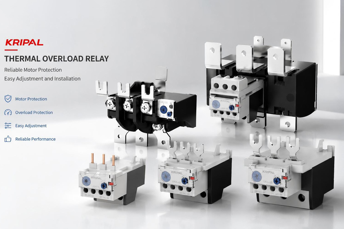
How Does a Thermal Overload Relay Work?
A thermal overload relay protects motors by monitoring the heating effect caused by excessive current.
Traditional thermal overload relays use bimetallic elements. When a motor operates under overload conditions, increased current generates heat through the relay’s heating elements. The bimetallic strips inside the relay are made from two different metals bonded together. Because the metals expand at different rates, the strips bend when heated. Once the bending reaches the designed operating point, the trip mechanism activates.
In a motor starter circuit, the overload relay normally does not disconnect the main power circuit directly. Instead, it operates through the contactor control circuit. When the relay trips, the normally closed auxiliary contact opens and removes power from the contactor coil, causing the contactor to disconnect the motor.
The Basic Trip Sequence
- The motor draws excessive current for an extended period.
- Heat builds up inside the overload relay.
- The relay mechanism activates.
- The NC auxiliary contact (95-96) opens.
- The contactor releases and disconnects the motor.
Modern electronic overload relays use current sensing technology instead of traditional thermal elements. They provide improved accuracy and may include additional functions such as phase imbalance detection, communication functions, and advanced motor monitoring.
How a Thermal Overload Relay Works with a Contactor
A thermal overload relay is usually installed together with a contactor to form a complete motor starter system.
The typical power circuit arrangement is:
Power Supply → Circuit Breaker → Contactor → Thermal Overload Relay → Motor
The contactor controls motor operation, while the overload relay provides protection against prolonged overload conditions.
During normal operation, the overload relay continuously monitors the motor current. If the motor experiences abnormal conditions, such as mechanical overload or phase imbalance, the relay trips and opens the control circuit.
Short-Circuit Protection Is Separate
It is important to understand that a thermal overload relay does not provide short-circuit protection. A circuit breaker or fuse is still required to protect the system against high fault currents caused by short circuits.
For a complete motor protection solution, the overload relay, contactor, and short-circuit protection device must be correctly selected and coordinated. Browse the KRIPAL contactors and relays range for coordinated components.
How to Set the Thermal Overload Relay Current
The overload relay current setting should be based on the motor nameplate full-load current (FLA). The motor manufacturer specifies the rated operating current, and this value should be used as the primary reference when adjusting the relay.
For a standard direct-on-line (DOL) motor starter, the overload relay is normally set close to the motor nameplate current.
DOL Example
Motor nameplate FLA = 18A → Overload relay setting ≈ 18A
For example, if a motor nameplate indicates a full-load current of 18A, the overload relay should typically be adjusted to approximately 18A.
The overload relay should not be adjusted higher simply to prevent nuisance tripping. Frequent trips usually indicate another problem, such as:
- Excessive mechanical load
- Voltage imbalance
- Poor motor ventilation
- Bearing or mechanical issues
- Incorrect motor selection
The correct approach is to identify and solve the underlying cause instead of increasing the protection setting.
Thermal Overload Relay Setting for Star-Delta Starters
Star-delta motor starters require special consideration because the overload relay setting depends on its installation position.
In many star-delta applications, the overload relay is installed inside the delta circuit. In this arrangement, the relay measures the motor phase current rather than the line current.
The approximate setting calculation is:
Star-Delta Setting
Overload Relay Setting = Motor FLA × 0.58
For example:
- A motor with a full-load current of 30A:
- 30A × 0.58 = approximately 17.4A
However, some star-delta starters install the overload relay in the motor supply line. In this case, the setting should normally match the motor nameplate current.
Therefore, before adjusting the overload relay, always confirm the starter wiring configuration and follow the relay manufacturer’s recommendations.
Understanding Thermal Overload Relay Trip Class
Trip class defines the response time of an overload relay under motor starting and overload conditions.
| Trip Class | Typical Application |
|---|---|
| Class 10 / 10A | Standard motors with normal starting time |
| Class 20 | Motors with longer acceleration time |
| Class 30 | Heavy inertia loads requiring extended starting time |
The correct trip class depends on the motor starting characteristics and application requirements.
Class 10 overload relays are commonly used for general industrial applications such as pumps, fans, and standard machinery.
For applications with higher starting torque or longer acceleration periods, such as large compressors or heavy-duty equipment, a higher trip class may be required.
Selecting the correct trip class helps prevent unnecessary tripping during motor starting while maintaining effective overload protection.
Manual Reset and Automatic Reset Selection
After an overload trip, the relay must return to its normal operating condition before the motor can restart.
Manual Reset
Manual reset is commonly selected for industrial machinery where unexpected restarting could create safety risks. Applications such as conveyors, production machines, and processing equipment usually require an operator to inspect the cause of the trip before restarting.
Automatic Reset
Automatic reset may be suitable for unattended equipment where continuous operation is important, such as remote pumps or ventilation systems.
The reset mode should always be selected according to the equipment safety requirements and operating environment.
Effect of Ambient Temperature on Overload Relay Setting
Because thermal overload relays respond to temperature, ambient conditions can influence their operating characteristics.
A relay installed in a high-temperature environment may trip earlier because the internal temperature rises faster. In very cold environments, the response may be slower.
Most modern overload relays include temperature compensation within their specified operating range. If the installation environment exceeds the recommended range, the manufacturer’s correction factors should be followed.
The overload setting should not be increased above the motor nameplate current unless the motor manufacturer provides a documented service factor that allows additional loading.
Thermal Overload Relay Wiring and Testing
Correct wiring is essential for reliable motor protection.
The most common auxiliary terminals are:
| Terminal | Function |
|---|---|
| 95-96 | Normally Closed (NC) trip contact |
| 97-98 | Normally Open (NO) alarm contact |
The 95-96 contact is normally connected in series with the contactor coil. When the overload relay trips, this contact opens and disconnects the contactor control circuit.
After installation, the protection system should be tested. Many overload relays include a test button that simulates a trip condition. This allows technicians to confirm that the contactor releases correctly and that the motor protection circuit operates properly.
Common Thermal Overload Relay Setting Mistakes
Incorrect overload relay adjustment can reduce motor protection effectiveness.
Common mistakes include:
Setting the relay too high
This may allow the motor to operate under excessive current conditions and increase the risk of overheating.
Setting the relay too low
This can cause unnecessary shutdowns during normal operation.
Using one overload relay for multiple motors
Each motor has different electrical and thermal characteristics. A dedicated overload relay should be used for each motor.
Ignoring the cause of repeated trips
Repeated overload trips usually indicate an underlying electrical or mechanical problem that should be investigated.
Thermal Overload Relay vs Circuit Breaker
Although both devices are used in motor protection systems, they provide different types of protection.
| Device | Main Function |
|---|---|
| Thermal Overload Relay | Protects motors from prolonged overload current |
| Circuit Breaker / Fuse | Protects against short circuits and high fault currents |
A reliable motor protection system requires both overload protection and short-circuit protection.
Frequently Asked Questions
Q: What happens if the overload relay is set above the motor nameplate current?
The motor may continue operating under excessive current conditions, causing overheating and possible winding damage. The setting should always follow the motor manufacturer’s specifications.
Q: Can one thermal overload relay protect two motors?
No. Each motor requires individual overload protection because different motors have different thermal characteristics and operating conditions.
Q: Do thermal overload relays protect against phase loss?
Many modern overload relays include phase loss or phase imbalance protection. However, dedicated phase monitoring devices may provide faster detection for certain applications.
Q: How can I tell if a thermal overload relay has failed?
Signs of failure include incorrect tripping behavior, failure to trip during testing, visible damage, or unreliable reset operation.
Conclusion
A correctly adjusted thermal overload relay is essential for reliable motor protection. Proper selection and adjustment require consideration of motor full-load current, starter configuration, trip class, reset mode, and operating environment.
By applying the correct setting method and performing regular maintenance, industrial users can reduce unexpected downtime, improve equipment reliability, and extend motor service life.
If you need assistance selecting the right thermal overload relay for your motor control application, contact KRIPAL technical engineers for professional support and customized motor protection solutions.
Related Resources
Explore Knowledge Center >

Need a matching KRIPAL product?
Share voltage, quantity and destination. An engineer will reply with options and lead time.
