


 Search
Knowledge Center
How to Set and Adjust a Thermal Overload Relay for Industrial Motor Protection
Learn how to set a thermal overload relay: FLA settings, DOL vs star-delta, trip classes, reset modes, temperature compensation and contactor wiring.
 July 12, 2026
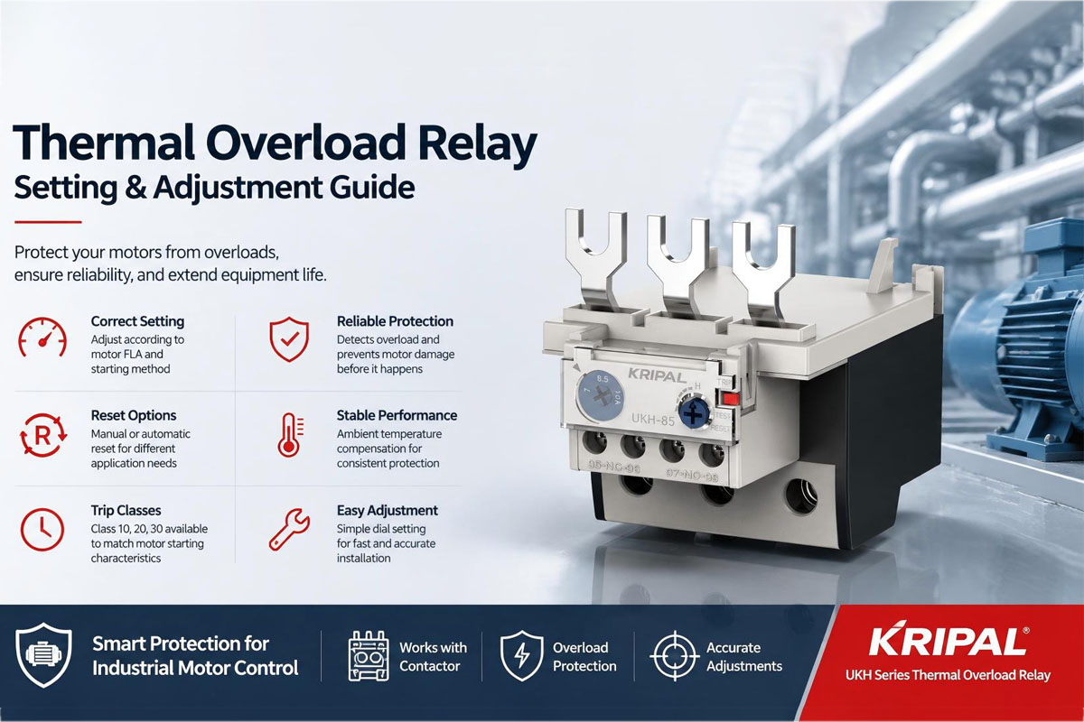
A thermal overload relay is a critical protection component in industrial motor control systems. It protects motors from damage caused by prolonged overcurrent conditions by detecting excessive heat and disconnecting the motor control circuit before serious winding damage occurs.
However, selecting and adjusting the correct overload relay setting is essential. If the setting is too low, the motor may experience frequent nuisance trips that interrupt production. If the setting is too high, the motor may continue operating under excessive current conditions, causing insulation deterioration and eventually motor failure.
Correct thermal overload relay adjustment requires more than simply setting the current dial. Engineers need to consider the motor nameplate current, starting method, trip class, reset mode, and installation environment.
This guide explains how to set a thermal overload relay correctly and how it works together with a contactor to provide reliable motor protection in industrial applications.
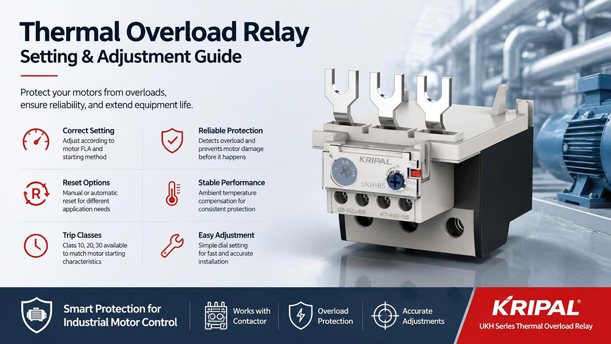
How Does a Thermal Overload Relay Work?
A thermal overload relay is normally installed together with a contactor to create a complete motor starter system. Unlike a circuit breaker, a thermal overload relay does not directly interrupt the main power circuit. Instead, it monitors the current flowing through the motor supply conductors. When the motor draws excessive current for an extended period, the heating elements inside the relay generate heat, causing the internal bimetal mechanism to operate.
When an overload condition occurs, the relay changes the state of its auxiliary contacts. The normally closed (NC) contact, usually identified as terminals 95-96, opens and interrupts power to the contactor coil. The contactor then releases its main contacts, disconnecting power from the motor. The normally open (NO) contact, usually identified as terminals 97-98, can be used for alarm indication or sending a fault signal to a PLC or monitoring system.
A thermal overload relay is designed specifically for motor overload protection, not short-circuit protection. Short circuits create extremely high current levels that require faster-acting protection devices such as MCBs, MCCBs, or fuses.
A typical motor protection arrangement using a contactor and overload relay is:
Power Circuit
Control Circuit
This combination provides both motor switching control and thermal protection.
How to Set a Thermal Overload Relay Correctly
The most important step in overload relay adjustment is selecting the correct current setting based on the motor nameplate data.
Before adjusting the relay, engineers should check the motor rated information, including:
- Rated current (Full Load Amperage / FLA)
- Rated voltage
- Frequency
- Service factor
- Motor duty rating
For a standard Direct-On-Line (DOL) motor starter, the overload relay setting is normally adjusted close to the motor nameplate full-load current. For example, if a three-phase motor has a rated current of 12 A, the overload relay should generally be adjusted around this value according to the motor manufacturer’s recommendation.
The final adjustment should also consider actual operating conditions, including ambient temperature, mechanical load, and motor service factor. The overload setting should always remain within the thermal capability of the motor.
Thermal Overload Relay Setting for Different Motor Starting Methods
The correct overload relay setting depends not only on motor current but also on the starting method used in the motor control system.
Direct-On-Line (DOL) Starter
In a DOL starter, the motor is connected directly to the supply through the contactor and overload relay. The relay measures the same current that flows through the motor windings. For this arrangement, the overload relay is normally adjusted close to: 100% of motor nameplate FLA.
DOL starting is the most common method for small and medium industrial motors because of its simple wiring and reliable operation.
Star-Delta (Wye-Delta) Starter
Star-delta starting reduces the starting current by initially connecting the motor windings in a star configuration before changing to delta operation. For star-delta systems, the overload relay setting depends on where the relay is installed.
When the relay is installed inside the delta circuit, it measures motor phase current rather than line current. Since phase current is approximately: Line current ÷ √3, the overload setting is normally around: 58% of the motor nameplate current.
However, some star-delta starters install the overload relay on the line side, where the setting calculation is different. Therefore, the wiring arrangement must always be checked before adjusting the overload relay.
Incorrect calculation in star-delta applications can result in either unnecessary tripping or insufficient motor protection.
VFD-Fed Motors
Variable Frequency Drives (VFDs) provide speed control and energy savings but also change the thermal behavior of motors. At reduced speeds, the motor’s built-in cooling fan may provide less airflow, which can increase the risk of overheating even when the current remains within the rated range.
For VFD applications, motor protection is often managed through the drive’s internal electronic thermal model. Additional overload protection may still be required depending on the application, motor type, and installation requirements.
Thermal Overload Relay Wiring with Contactor
A thermal overload relay is normally used together with a contactor because the relay itself does not directly switch the motor power circuit. The contactor controls the motor’s main power supply, while the overload relay monitors the motor current and provides protection during abnormal operating conditions.
A typical three-phase motor starter wiring arrangement is shown below:
Main Power Circuit
Control Circuit
When the motor experiences a prolonged overload condition, the overload relay opens the 95-96 auxiliary contact. This interrupts the contactor coil circuit, causing the contactor to disconnect power from the motor. For industrial motor control panels, selecting a properly matched contactor and thermal overload relay combination is important to ensure reliable operation and long service life.
Manual Reset vs Automatic Reset of Thermal Overload Relay
Most modern thermal overload relays provide manual and automatic reset options. The correct selection depends on the application requirements and safety considerations.
Manual Reset Mode
In manual reset mode, the overload relay remains in the tripped condition until an operator manually presses the reset button. This mode is commonly preferred for industrial machinery where unexpected automatic restart could create a safety risk. Applications such as conveyors, processing equipment, mixers, and machine tools usually require operators to identify the cause of overload before restarting the motor. Manual reset improves operational safety because it prevents a motor from restarting automatically after a fault condition.
Automatic Reset Mode
In automatic reset mode, the overload relay automatically returns to the normal operating position after the internal thermal elements cool down. This mode may be suitable for unattended equipment where automatic restart does not create a hazard, such as remote pumps, HVAC fans, or certain compressor systems. However, automatic reset should be selected carefully because repeated restarting under an unresolved overload condition may cause additional stress to the motor.
Understanding Thermal Overload Relay Trip Classes
Different motors have different starting characteristics. Some motors accelerate quickly, while others require a longer starting time because of high mechanical inertia. Thermal overload relays are classified according to their trip characteristics. According to IEC 60947-4-1, the trip class defines the maximum operating time when the relay is tested at 7.2 times the adjusted current.
The most common trip classes are:
| Trip Class | Typical Trip Time | Common Applications |
|---|---|---|
| Class 10 | About 10 seconds | Pumps, fans, general motors |
| Class 20 | About 20 seconds | Conveyors, heavy loads |
| Class 30 | About 30 seconds | Centrifuges, large blowers |
Selecting the correct trip class is important. A Class 10 overload relay used on a high-inertia machine may trip during normal motor starting, while an unsuitable high trip class may reduce the effectiveness of motor protection. The correct selection should consider the motor starting time, mechanical load characteristics, and manufacturer’s recommendations.
The Importance of Ambient Temperature Compensation
Thermal overload relays operate based on heat generated by current flow, which means surrounding temperature can influence their performance. In a high-temperature environment, such as a control cabinet installed near heat-producing equipment or outdoors under direct sunlight, the overload relay may reach its operating temperature faster. In a cold environment, the relay may respond more slowly.
To improve accuracy, high-quality thermal overload relays use temperature compensation technology. This helps maintain stable protection characteristics when ambient temperature changes. When selecting an overload relay for industrial applications, engineers should consider the control cabinet environment, operating temperature range, and installation conditions.
The KRIPAL UKH series thermal overload relay is designed with ambient temperature compensation to provide stable motor protection performance in industrial motor control applications. See the UKH-22 thermal overload relay for adjustable current settings from 0.1 to 22A with 3P, 1NO, and 1NC contact configuration.
How to Select the Right Thermal Overload Relay
Choosing the correct thermal overload relay requires evaluating several key application factors:
- Motor Rated Current — The overload relay current range should match the motor nameplate full-load current.
- Starting Method — The setting method depends on whether the motor uses DOL, star-delta, soft starter, or VFD control.
- Trip Class Requirement — Select the appropriate trip class according to motor acceleration time and mechanical load.
- Environmental Conditions — Consider cabinet temperature, installation location, and the need for temperature compensation.
- Reset Mode — Choose manual or automatic reset according to operational safety requirements.
For industrial motor protection systems, the KRIPAL UKH series provides adjustable current settings, reliable overload protection, and stable operation for a wide range of motor control applications.
Frequently Asked Questions
Q: What current should a thermal overload relay be set to?
For most direct-on-line motor starters, the overload relay should normally be adjusted close to the motor nameplate full-load current according to manufacturer recommendations.
Q: Can a thermal overload relay protect against short circuits?
No. A thermal overload relay protects against prolonged overload conditions. Short-circuit protection must be provided by separate devices such as MCBs, MCCBs, or fuses.
Q: Why does a thermal overload relay trip during motor starting?
Common causes include incorrect trip class selection, excessive mechanical load, incorrect current adjustment, or problems with the motor or driven equipment.
Q: What is the difference between Class 10 and Class 20 overload relays?
Class 10 overload relays trip faster and are suitable for standard motors, while Class 20 relays allow longer starting times for motors with heavier loads and higher inertia.
Conclusion
Correctly setting and adjusting a thermal overload relay is essential for protecting industrial motors from overheating and premature failure. A reliable motor protection system requires more than simply matching the relay current range. Engineers must consider motor full-load current, starting method, trip class, reset mode, and environmental conditions.
When properly selected and adjusted, a thermal overload relay works together with a contactor to provide effective motor protection, reduce unexpected downtime, and extend equipment service life.
For industrial applications requiring dependable motor protection, KRIPAL UKH series thermal overload relays provide a practical solution with adjustable settings and reliable performance. Contact KRIPAL for technical support and product selection assistance.
Related Resources
Explore Knowledge Center >

Need a matching KRIPAL product?
Share voltage, quantity and destination. An engineer will reply with options and lead time.
