Search
News
Prospective Fault Current Explained: How to Calculate and Measure PSCC and PFC
Learn how to calculate and measure prospective fault current, including PSCC and PFC. Step-by-step guide to fault current calculation for electrical safety.
![]() May 01, 2026
May 01, 2026
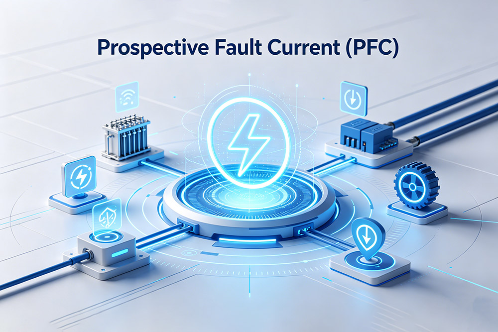
Electrical systems are designed to operate safely under normal conditions, but faults such as short circuits and earth faults can cause extremely high currents to flow within milliseconds. The level of current available during a fault is known as the Prospective Fault Current (PFC).
Understanding PFC and Prospective Short-Circuit Current (PSCC) helps electricians, engineers, and contractors select protective devices with suitable breaking capacities and maintain safe operation across installations.
What Is Prospective Fault Current (PFC)?
Prospective Fault Current is the maximum current that could flow in an electrical circuit during a fault condition if there were negligible impedance from protective devices. It represents the highest possible fault current available at a particular point in the installation.
PFC is influenced by several factors, including:
- Supply transformer size and impedance
- Distance from the transformer
- Cable length and conductor size
- Network impedance
- Earthing arrangement
- Parallel power sources such as generators or UPS systems
Higher fault currents generally occur closer to the supply transformer where impedance is lower.
Difference Between PFC, PSCC and PEFC
The term PFC is often used as a general description of available fault current, while PSCC and PEFC describe specific fault types.
Prospective Short-Circuit Current (PSCC)
PSCC refers to the fault current between live conductors, such as:
- Line-to-line faults
- Line-to-neutral faults
- Three-phase faults
Three-phase faults usually produce the highest fault current values.
Prospective Earth Fault Current (PEFC)
PEFC refers to the current flowing during a line-to-earth fault. The value depends heavily on the earthing system and earth fault loop impedance.
In many electrical inspections, both PSCC and PEFC are measured, and the higher value is recorded as the installation’s PFC.
Why Fault Current Matters
Protective devices such as circuit breakers, RCBOs, MCCBs, and fuses are designed to disconnect fault currents safely before damage occurs within an electrical installation.
If the prospective fault current exceeds the breaking capacity of the protective device, the equipment may fail during a fault condition, potentially causing severe damage to switchgear and increasing safety risks.
Accurate fault current calculations help engineers and electricians select suitable switchgear ratings, coordinate protective devices correctly, reduce arc flash risks, and verify that disconnection times comply with electrical wiring regulations.
For example, a 6kA MCB should not be installed on a circuit where the measured fault current exceeds 6kA, as the breaker may not be capable of interrupting the fault safely.
How to Calculate Prospective Short-Circuit Current
The most common formula used for calculating PSCC is:
Where:
| Isc = |
|
- Iscprospective short-circuit current (A)
- V = system voltage (V)
- Z = total circuit impedance (Ω)
The total impedance includes:
- Transformer impedance
- Cable impedance
- Distribution board impedance
- Protective device impedance
As impedance decreases, fault current increases.
Example PSCC Calculation
Consider a 400V three-phase system supplied by a 500kVA transformer with 5% impedance.
Step 1: Calculate Full Load Current
| IFL = |
|
The full-load current is approximately 722A.
Step 2: Calculate Short-Circuit Current
| ISC = |
|
The calculated prospective short-circuit current is approximately 14.4kA.
This value would then be compared against the interrupting capacity of the protective devices installed within the system.
Factors Affecting PSCC and PFC
Several installation characteristics can increase or reduce fault current levels.
Transformer Size
Larger transformers generally produce higher fault currents because they have lower impedance. As transformer capacity increases, more current can flow during a fault condition.
For example, commercial and industrial transformers usually provide higher prospective fault currents than smaller residential transformers.
Transformer impedance also affects fault current levels. Lower impedance allows higher fault current, while higher impedance helps limit it.
Cable Length
Longer cables increase circuit impedance, which reduces the available fault current at the point of fault. As cable length increases, electrical resistance also increases, limiting the amount of current that can flow during a short circuit or earth fault.
For this reason, circuits located farther away from the power source usually have lower prospective fault current levels.
Conductor Size
Larger conductors have lower electrical resistance, allowing fault current to flow more easily through the circuit. As conductor size increases, the impedance of the circuit decreases, which can result in a higher prospective fault current.
Smaller conductors create higher resistance, which may help limit fault current levels but can also increase voltage drop and heat generation under load conditions.
Fault Type
Different types of electrical faults produce different levels of fault current. A three-phase fault typically generates the highest fault current because all three phases are directly short-circuited together with minimal impedance in the fault path.
A phase-to-phase fault usually produces a lower current level since only two phases are involved. An earth fault generally results in an even lower fault current because the magnitude is heavily influenced by the impedance of the earth return path and the earthing system configuration.
Supply Position
Installations located close to substations often experience higher PFC values due to lower network impedance.
How Prospective Fault Current Is Measured
In practice, electricians commonly measure PFC using a multifunction installation tester (MFT) or dedicated loop tester.
The instrument briefly applies a test load and calculates the available fault current from the measured impedance.
Measuring PSCC
PSCC is typically measured between:
- Line and Neutral
- Line and Line (three-phase systems)
Measuring PEFC
PEFC is measured between:
- Line and Earth
The highest reading is normally recorded as the PFC value for the installation.
Typical PFC Test Procedure
A typical PFC test begins by isolating downstream circuits where necessary to ensure safe testing conditions. The tester is then connected at the origin of the installation or directly at the distribution board.
After selecting the PFC or loop impedance test mode on the instrument, measurements are taken between Line and Neutral to determine the Prospective Short-Circuit Current (PSCC), and between Line and Earth to determine the Prospective Earth Fault Current (PEFC).
Once both readings have been obtained, the higher value is usually recorded as the installation’s prospective fault current.
PFC testing is commonly performed at main switchboards, distribution boards, final circuits, and commercial switchgear panels to verify that protective devices are capable of safely interrupting potential fault currents.
High and Low Fault Current Problems
Both excessively high and excessively low fault currents can create protection issues.
High PFC
Very high prospective fault current levels can create serious safety and equipment risks in an electrical installation. If the fault current exceeds the breaking capacity of a circuit breaker, the device may fail to disconnect the fault safely.
High fault currents can also increase arc flash energy and place excessive thermal and mechanical stress on switchgear and distribution equipment. In such cases, higher kA-rated protective devices are required to safely handle fault conditions.
Low PFC
Low fault current can also cause problems because some protective devices may not operate quickly enough to disconnect the fault safely.
Common Methods Used to Reduce Fault Current
Where fault current levels are too high, engineers may take several measures to reduce the risk and ensure the electrical system remains safe and compliant.
One common solution is to install higher-rated circuit breakers that can safely interrupt larger fault currents without damage. Current-limiting fuses may also be used to reduce the peak fault energy and protect downstream equipment.
In some cases, engineers increase cable impedance by selecting longer cable runs or smaller conductors, which helps limit the amount of fault current flowing through the system.
Transformer impedance adjustments can also reduce prospective fault current levels by restricting the current available during a fault condition. In larger installations, the overall distribution layout may be redesigned to improve fault current management, enhance protection coordination, and reduce stress on electrical equipment.
PFC and Protective Device Selection
Every protective device has a rated breaking capacity, such as:
- 6kA
- 10kA
- 25kA
- 36kA
The device rating must exceed the maximum prospective fault current at its installation point.
For example:
| Measured PFC | Minimum Breaker Rating |
| 4kA | 6kA breaker |
| 8kA | 10kA breaker |
| 18kA | 25kA breaker |
This is why fault current testing is normally performed before selecting or replacing switchgear.
Conclusion
Prospective Fault Current testing forms part of electrical verification, commissioning, and system design. Accurate PSCC and PEFC values help ensure that protective devices can disconnect faults safely and that installations remain compliant with electrical standards.
Explore our range of electrical protection solutions designed for safe and reliable installations.
Contact us today for product information, technical support, or application guidance.
Related Resources
Explore News >
How can we assist you?
Tell us a bit more so we can route your request to the right expert.