


 Search
Knowledge Center
Motor Protection Circuit Breaker Selection Guide: MPCB vs MCB Plus Contactor Plus Thermal Relay
Compare an MPCB with the traditional MCB, contactor and thermal overload relay starter. Learn IEC 60947-4-1 coordination and how to select the right MPCB.
 July 04, 2026
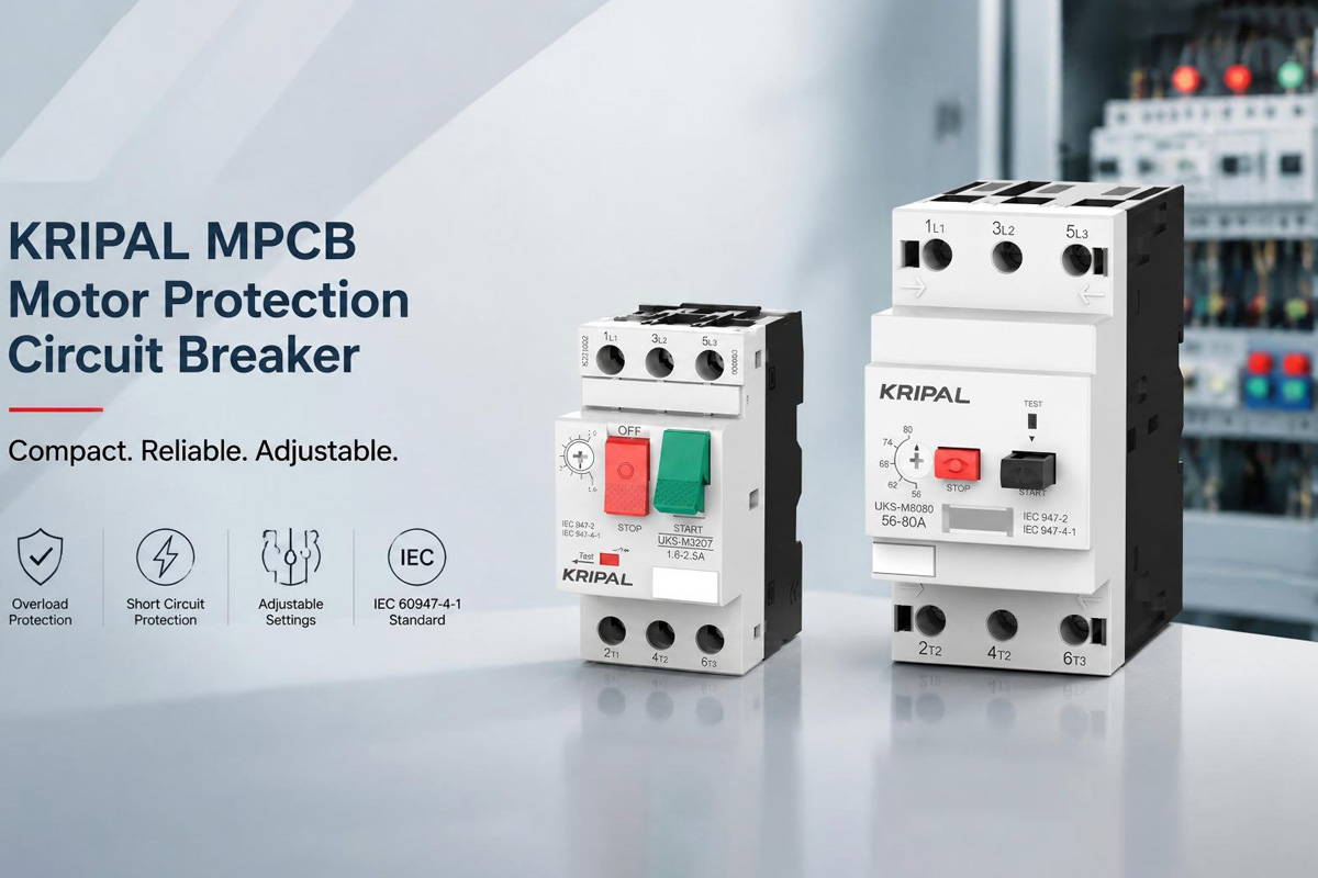
Electric motors require reliable protection against overload, short circuits, and abnormal operating conditions. During direct-on-line starting, a motor can draw several times its rated current, typically around 5 to 8 times depending on motor design and starting method. The protection device must allow this temporary starting current while still responding to genuine faults.
For motor protection applications, two common solutions are widely used: the traditional combination of an MCB, contactor, and thermal overload relay, or a dedicated Motor Protection Circuit Breaker (MPCB).
This guide explains the differences between these two solutions, IEC requirements, and how to select the correct MPCB for motor applications.
MCB + Contactor + Thermal Overload Relay Solution
A traditional motor starter uses three separate devices to complete motor protection and control.
01
MCB
The MCB provides short-circuit protection.
03
Thermal Overload Relay
The thermal overload relay protects the motor against prolonged overcurrent conditions.
The main advantage of this approach is flexibility. Each component performs a dedicated function, allowing engineers to replace or adjust individual devices when system requirements change. For example, if a motor rating changes, only the overload relay may need to be replaced. Different control voltages can also be handled by selecting a suitable contactor coil.
However, this solution requires more panel space and wiring. Multiple devices increase installation time and create more connection points that require inspection and maintenance.
Therefore, the traditional MCB + contactor + overload relay solution is often selected for applications where flexibility and control options are more important than compact design.
Motor Protection Circuit Breaker (MPCB)
A Motor Protection Circuit Breaker integrates the main protection functions required for motor applications into one compact device. It combines adjustable thermal overload protection, adjustable magnetic short-circuit protection, and manual motor switching capability.
KRIPAL UKS-M Series
The KRIPAL UKS-M32 and UKS-M80 MPCB series are designed for motor applications up to 80A, providing adjustable protection settings and compact installation for motor control panels.
Compared with a traditional motor starter combination, an MPCB reduces the number of components required and simplifies panel design. It is particularly suitable for applications where space saving, faster installation, and simplified protection coordination are important.
However, an MPCB must be selected according to the motor nameplate current. Because the protection functions are integrated into one device, replacing only one individual component is not possible if the motor requirements change significantly.
It should also be noted that an MPCB does not always replace a contactor. For manual motor operation, an MPCB may provide sufficient switching capability. However, applications requiring PLC control, BMS integration, or remote start/stop operation normally still require a contactor.
MPCB vs MCB + Contactor + Overload Relay
The main difference between these two solutions is the level of integration. A traditional starter separates protection and control functions into different devices, while an MPCB combines the main protection functions into one unit.
MCB + Contactor + OLR
- Separate components
- Maximum flexibility
- Larger panel footprint
- More wiring connections
MPCB
- Integrated device
- Adjustable thermal and magnetic protection
- Compact installation
- Reduced wiring
| Feature | MCB + Contactor + OLR | MPCB |
|---|---|---|
| Protection method | Separate components | Integrated device |
| Overload protection | Thermal overload relay | Adjustable thermal protection |
| Short-circuit protection | MCB | Adjustable magnetic protection |
| Panel space | Larger | More compact |
| Wiring complexity | Higher | Reduced |
| Remote motor control | Through contactor | Contactor required when automatic control is needed |
Both solutions are technically suitable for motor protection. The correct choice depends on installation requirements, motor control methods, available space, and maintenance expectations.
Understanding IEC 60947-4-1 and Motor Coordination
Motor starter systems are commonly evaluated according to IEC 60947-4-1, which covers contactors and motor starters. The standard defines coordination requirements between motor starter components and short-circuit protective devices.
Type 1 Coordination
Type 1 coordination means that after a short circuit, the fault is safely cleared but some components may be damaged and require replacement. This approach is acceptable where downtime and replacement costs are manageable.
Type 2 Coordination
Type 2 coordination provides a higher level of protection. After a short circuit, the starter should remain functional. Some contact welding is acceptable, but the contacts must be separable without replacing the device, and no significant damage should occur to other components.
Type 2 coordination is preferred in many industrial applications because it reduces downtime and improves system reliability.
The KRIPAL UKS series supports Type 2 coordination when installed with the correct upstream protective device according to the coordination requirements.
How to Select the Right MPCB for a Motor
Correct MPCB selection begins with the motor nameplate. Engineers should consider the motor rated voltage, full-load current, starting method, and installation conditions before choosing a protection device.
The basic selection process includes:
1. Select the correct current range
The MPCB current range should include the motor full-load current.
For example, a three-phase motor operating at 400V AC with a rated current of 22A requires an MPCB suitable for the 22A range, such as the KRIPAL UKS-M32 series.
2. Adjust protection settings
The thermal overload setting should normally follow the motor nameplate current. Final adjustment may depend on application conditions such as ambient temperature, motor service factor, and installation environment.
The magnetic trip setting must allow normal motor starting current while providing short-circuit protection. The correct setting depends on MPCB design, motor characteristics, and starting method. Motors with higher starting current may require a higher magnetic setting to prevent nuisance tripping.
Before installation, engineers should also verify the MPCB breaking capacity and confirm that it is suitable for the prospective short-circuit current at the installation point. Type 2 coordination requirements should also be checked with the upstream protective device.
When Should You Choose an MPCB?
An MPCB is a practical choice when compact design and simplified installation are important. It is commonly used in motor control panels where motor specifications are stable and reducing assembly time is valuable.
Typical applications include:
- Compact control panels
- Industrial machinery
- Pumps and compressors
- HVAC systems
- Conveyor systems
The traditional MCB + contactor + overload relay solution remains suitable for applications requiring greater flexibility, frequent motor changes, or complex control requirements. Browse the full KRIPAL contactors and relays range to build a coordinated starter.
FAQ
Q: Can an MPCB replace a contactor?
Not always. An MPCB provides motor protection and manual switching, but applications requiring PLC, BMS, or remote start/stop control normally require a contactor.
Q: What is the difference between an MPCB and an MCB?
An MCB is designed mainly for general circuit protection with fixed protection characteristics. An MPCB is specifically designed for motors and provides adjustable overload and magnetic protection suitable for motor starting conditions.
Q: How do I choose the correct MPCB size?
The MPCB should be selected according to the motor full-load current, operating voltage, starting method, and short-circuit requirements. The selected current range should match the motor nameplate current.
Q: Can one MPCB protect multiple motors?
Generally, no. Each motor should have independent overload protection matched to its own rated current.
Conclusion
Both MPCB and MCB + contactor + thermal overload relay solutions are widely used for motor protection. A traditional motor starter provides flexibility through separate components, while an MPCB offers a compact solution by integrating protection functions into one device.
For applications requiring space-saving design, adjustable protection, and simplified installation, KRIPAL UKS-M32 and UKS-M80 Motor Protection Circuit Breakers provide a reliable solution for industrial motor applications. Contact our engineers for coordination tables and selection support.
Related Resources
Explore Knowledge Center >

Need a matching KRIPAL product?
Share voltage, quantity and destination. An engineer will reply with options and lead time.
