


 Search
Knowledge Center
How to Wire a Consumer Unit: Step-by-Step Installation and Safety Guide
Step-by-step consumer unit wiring: main switch, RCBO installation, busbar torque, neutral/earth termination and BS 7671 testing before energizing.
 July 10, 2026
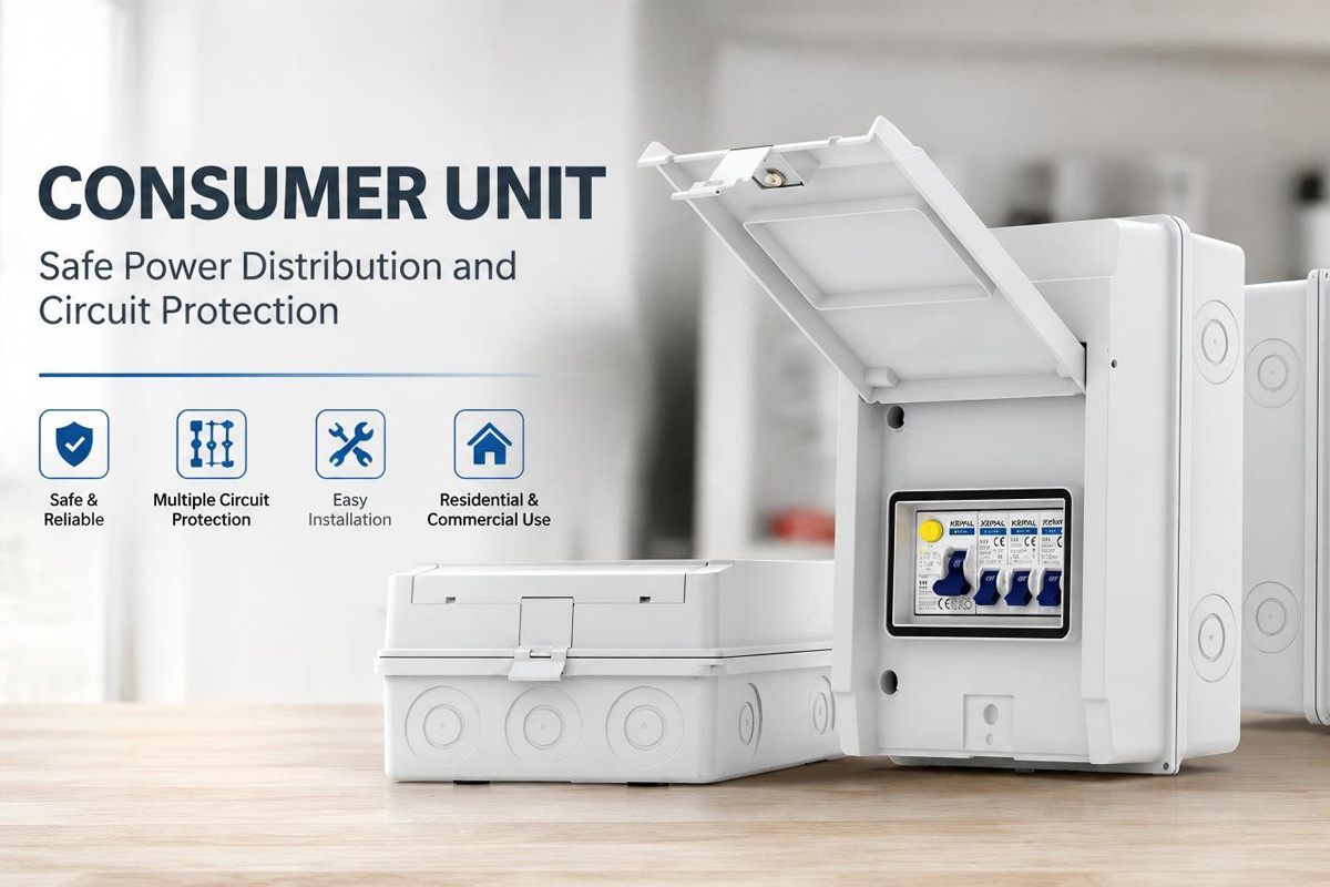
A consumer unit, also known as a distribution board or fuse box, is the central control point of a building’s electrical installation. It receives the incoming mains supply and distributes electricity safely to individual final circuits while providing essential protection against overloads, short circuits, and earth leakage faults.
A correctly installed consumer unit ensures that circuits can be safely controlled, tested, and maintained throughout the electrical system’s service life. Modern consumer units increasingly use RCBO protection instead of traditional split-load arrangements, combining residual current protection and overcurrent protection in a single device to provide individual circuit protection and reduce unnecessary power interruptions.
This guide explains the basic wiring sequence of a modern consumer unit, including main switch connections, RCBO installation, busbar connections, neutral and earth termination, and essential testing procedures based on BS 7671 IET Wiring Regulations.
Safety First: Isolation and Verification Before Wiring
Before working inside any consumer unit, the electrical supply must be safely isolated and verified. Unlike many electrical devices, a consumer unit may contain permanently live parts even when the main switch is turned off. The incoming supply cables from the utility meter can remain energized unless the upstream supply has been disconnected by the network operator.
Before installation or modification:
Isolate the Electrical Supply
Switch off the upstream isolator where available and follow the correct isolation procedure for the installation. Lock-off devices should be used where required to prevent accidental reconnection.
Verify the Circuit Is Dead
Use an approved two-pole voltage indicator to confirm that no dangerous voltage is present before touching any conductors. Non-contact voltage detectors can be useful as a preliminary check but should not be relied upon as the only method for proving dead.
Prove the Test Equipment
A voltage tester should be checked before and after testing using an appropriate proving unit or known live source. This confirms that the tester is functioning correctly throughout the isolation process.
Electrical safety procedures are not optional. A professional installation requires both correct wiring methods and reliable verification procedures.
Consumer Unit Components and Wiring Layout
A modern consumer unit consists of several key components that work together to provide electrical distribution and protection. Understanding the function of each component is essential before starting the wiring process.
Main Switch
The main switch provides a means of isolating the entire consumer unit from the incoming supply. In many UK installations, a double-pole main switch is commonly used because it disconnects both the line and neutral conductors. The current rating is typically selected according to the installation requirements and may commonly range from 80A to 125A.
Protective Devices: MCBs and RCBOs
Traditional consumer units often use MCBs combined with one or two RCDs. However, modern installations increasingly adopt all-RCBO configurations.
An RCBO combines:
- Overcurrent protection from an MCB
- Residual current protection from an RCD
This allows each individual circuit to have dedicated protection, reducing the risk that one faulty circuit will interrupt power to the entire building.
For applications requiring reliable circuit protection, manufacturers supply different RCBO solutions including single-pole, double-pole, and multi-pole versions depending on system requirements.
Busbar
The copper busbar distributes the incoming line supply from the main switch to multiple protective devices within the consumer unit. Proper installation requires accurate alignment, secure terminal engagement, and tightening according to the manufacturer’s specified torque settings. Incorrect installation or loose connections can increase contact resistance, leading to excessive heat generation, electrical arcing, and potential fire hazards.
Neutral and Earth Bars
The neutral bar provides termination points for circuit neutral conductors, while the earth bar connects protective earth conductors (CPCs) and the main earthing conductor.
All conductors must be correctly identified, securely terminated, and arranged to allow easy inspection and maintenance.
Step-by-Step Consumer Unit Wiring Process
Step 1: Mount the Consumer Unit Enclosure and Prepare Cable Entries
Install the consumer unit enclosure securely on the wall according to the manufacturer’s instructions.
The location should provide:
- Easy access for operation and maintenance
- Adequate working space
- Protection from environmental damage
For UK domestic installations, consumer units are commonly installed at a convenient operating height while following applicable installation requirements.
When cables enter a metal enclosure, suitable protection such as cable glands, grommets, or appropriate entry accessories should be used to prevent insulation damage from sharp edges.
Cable preparation is an important part of installation quality. Conductors should be routed neatly with sufficient length for future inspection without excessive loops inside the enclosure.
Step 2: Install and Connect the Main Switch
The main switch is normally installed on the DIN rail according to the consumer unit design.
The incoming supply conductors are connected to the main switch terminals:
- Line conductor (brown) → L terminal
- Neutral conductor (blue) → N terminal
Before tightening terminals:
- Strip conductors to the correct length
- Ensure no exposed copper remains outside the terminal
- Tighten using the manufacturer’s recommended torque value
Correct torque is essential because both over-tightening and under-tightening can damage terminals or reduce connection reliability.
Step 3: Install RCBO Protective Devices
After the main switch installation, RCBOs are installed onto the DIN rail according to the required circuit arrangement.
For an all-RCBO consumer unit configuration:
- The final circuit line conductor connects to the RCBO output terminal.
- The circuit neutral connection must follow the RCBO manufacturer’s design.
- Some RCBOs use a dedicated neutral flying lead connected to the neutral bar.
- Other designs use integrated neutral connections or dedicated neutral systems.
The circuit neutral must always pass through the RCBO’s sensing mechanism. Connecting the neutral incorrectly can prevent the RCBO from detecting residual current faults.
Each circuit should be clearly labeled to allow quick identification during testing, maintenance, or fault finding.
Step 4: Install and Torque the Busbar Correctly
The copper busbar is responsible for distributing the incoming line supply from the main switch to the protective devices installed on the DIN rail.
During installation:
- Ensure the busbar teeth are correctly aligned with the protective device terminals.
- Confirm that each connection point is fully engaged.
- Tighten all terminals according to the manufacturer’s specified torque value.
A calibrated torque screwdriver should be used whenever possible. Incorrect torque can create unreliable electrical connections.
A loose terminal may increase contact resistance, causing:
- Excessive heat generation
- Micro-arcing
- Terminal damage
- Possible fire risk
For this reason, professional consumer unit installation requires not only correct component selection but also accurate mechanical tightening procedures.
Step 5: Terminate Neutral and Earth Conductors
The final stage of internal wiring involves connecting all neutral and protective conductors correctly.
Earth Connections
The main earthing conductor and all circuit protective conductors (CPCs) must be securely connected to the earth bar.
Good practice includes:
- Keeping CPC routing neat and organized
- Avoiding unnecessary conductor loops
- Ensuring every terminal is properly tightened
The earth connection provides an essential fault current path, allowing protective devices to operate quickly under fault conditions.
Neutral Connections
Neutral conductors from final circuits must be connected according to the consumer unit and protective device design.
In an RCBO consumer unit:
- The neutral connection must pass through the RCBO sensing system.
- Circuit neutrals should not be incorrectly connected directly to a standard neutral bar if this bypasses the RCBO protection function.
Incorrect neutral wiring can prevent residual current protection from operating correctly.
A well-organized neutral arrangement also makes future testing and troubleshooting significantly easier.
Testing and Inspection Before Energizing the Consumer Unit
Installing the wiring is only one part of a safe consumer unit installation. Before energizing the system, electrical testing must be completed to verify that the installation meets safety requirements. A qualified electrician should carry out appropriate inspection and testing procedures using calibrated test equipment.
Important tests include:
Continuity of Protective Conductors
The protective earth path must be verified to ensure every CPC provides a continuous, low-resistance connection back to the earth terminal. This confirms that fault currents can safely return to the supply source and allow protective devices to disconnect the circuit.
Ring Final Circuit Testing
Where ring final circuits are installed, continuity testing should be carried out to verify the integrity of the line conductor, neutral conductor, and protective conductor. This ensures that the ring circuit has been correctly connected, with no open circuits, incorrect terminations, or wiring faults that could affect the safety and performance of the electrical installation.
Insulation Resistance Testing
Insulation resistance testing is performed using a suitable multifunction tester, commonly at 500V DC for low-voltage installations.
Testing is normally carried out between:
- Line and Neutral
- Line and Earth
- Neutral and Earth
BS 7671 requires a minimum insulation resistance value of 1MΩ, although correctly installed new wiring normally achieves much higher readings. Sensitive electronic equipment, surge protection devices, and certain RCBO designs may need to be disconnected or considered carefully during insulation testing to avoid damage.
Functional Testing
After dead testing has been completed, the consumer unit should undergo functional testing to confirm that all protective devices operate correctly. This includes verifying RCD and RCBO operation, checking the performance of protective devices, and confirming that circuit labels and identification are accurate. The consumer unit should only be energized after all required inspection and testing procedures have been successfully completed.
Consumer Unit Wiring Diagram: Understanding the Connection Layout
A clear wiring diagram is one of the most useful tools when designing or installing a consumer unit.
A typical modern RCBO consumer unit wiring layout includes:
Incoming Supply → Main Switch → Busbar → RCBOs → Final Circuits
with separate:
- Neutral connections
- Protective earth connections
A properly designed layout improves:
- Safety
- Fault diagnosis
- Maintenance efficiency
- Future expansion capability
For electrical contractors and panel builders, choosing reliable protective devices such as RCBOs, MCBs, and isolator switches is essential for creating safe and compliant distribution systems.
Frequently Asked Questions (FAQs)
What is the difference between an MCB and an RCBO?
An MCB protects against overload and short-circuit faults, while an RCBO combines MCB protection with residual current protection to detect earth leakage faults.
Why are RCBO consumer units becoming more popular?
RCBO consumer units provide individual circuit protection. If one circuit develops a fault, only that circuit is disconnected instead of affecting multiple circuits throughout the building.
Can I replace an old fuse box with an RCBO consumer unit?
Replacing an existing consumer unit requires inspection, testing, and compliance with applicable electrical regulations. In many cases, upgrading to an RCBO-based system can improve circuit protection and fault isolation.
What products are commonly used inside a modern consumer unit?
A modern consumer unit typically includes main isolator switches, RCBOs, MCBs, surge protection devices, neutral and earth terminals, and DIN rail accessories. These components work together to provide safe and reliable electrical distribution for residential, commercial, and light industrial applications.
Conclusion
A consumer unit is the central protection point of an electrical installation. Correct wiring requires careful planning, suitable protective devices, accurate termination, and comprehensive testing.
Modern installations are increasingly moving toward RCBO-based consumer units because they provide improved circuit-level protection and reduce unnecessary interruptions.
By following correct installation principles, maintaining proper cable management, applying accurate torque settings, and completing all required testing procedures, electricians can create electrical distribution systems that are safer, easier to maintain, and more reliable.
For electrical contractors, distributors, and system integrators, selecting high-quality protection devices such as RCBOs, MCBs, and isolator switches is an important step toward achieving dependable electrical installations that meet modern safety expectations. Browse KRIPAL consumer unit and circuit protection options, or contact our team for project support.
Related Resources
Explore Knowledge Center >

Need a matching KRIPAL product?
Share voltage, quantity and destination. An engineer will reply with options and lead time.
