Search
 August 06, 2026
A power factor correction (PFC) panel is one of the places in a low-voltage installation where a contactor can suffer premature failure even when the device itself is correctly manufactured and the wiring is correct.
The problem is often the switching duty rather than a product defect. Capacitor banks produce high-current transients during energization, and a standard motor contactor is not necessarily designed to handle repeated capacitor-switching conditions.
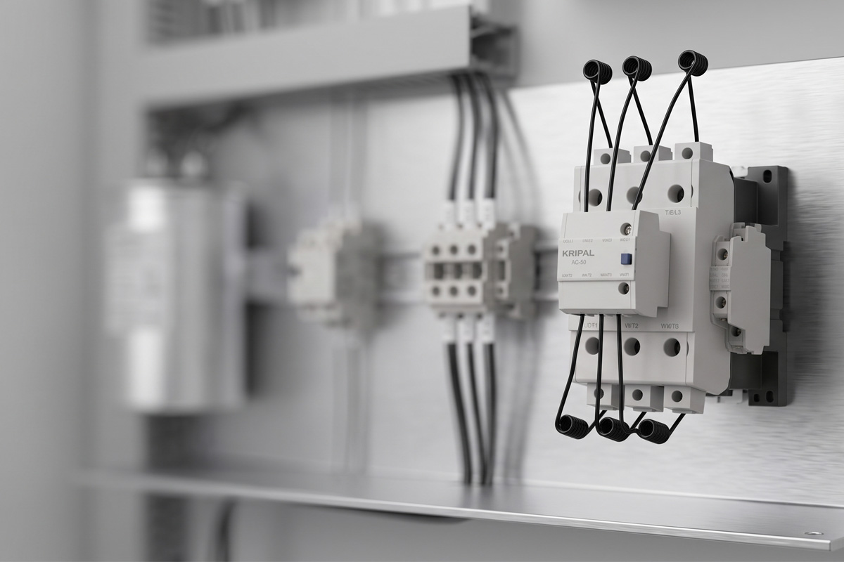
This guide explains why standard motor contactors can fail prematurely in capacitor-bank applications. It then covers what the AC-6b utilization category means, how capacitor-switching inrush is generated, and how to select a contactor from a kvar rating rather than from an ampere figure alone. The KRIPAL UKC1 capacitor duty contactor range is used as the worked example.
Why a Motor Contactor Fails in a Capacitor Bank
At the instant of energization, a discharged capacitor initially presents very low impedance, so the first current transient can be extremely high. Unlike a motor winding, there is no motor back EMF to limit the initial current. The magnitude of the transient is determined largely by the source impedance, transformer characteristics, and the inductance of the busbars and cables.
The consequence is a current pulse that can be many times higher than the capacitor’s steady-state current. Several effects occur at the same time, and repeated exposure can accelerate contact erosion and increase the risk of contact welding.
For an isolated capacitor bank, the peak inrush can reach several tens of times the rated capacitor current. When a new bank is switched in parallel with capacitor stages that are already energized, the transient can become substantially higher because energy can flow between the energized and incoming banks. The actual peak is installation-dependent and should not be treated as a fixed multiplier.
The transient can also contain high-frequency oscillation. Manufacturer application data commonly places the transient frequency in the several-kilohertz range, with approximately 3 kHz to 15 kHz possible depending on the network and switching arrangement. These high-frequency current pulses occur during a very short interval, rather than as a continuous 50 or 60 Hz load.
Contact tips therefore experience electrical stress that is not represented by the steady-state current alone. At opening, the capacitor current naturally passes through zero, but the capacitor can still retain a substantial voltage. The resulting recovery voltage across the opening contacts can increase the risk of restriking if the contactor is not designed for capacitor-switching duty.
This is why a contactor that performs correctly on a motor circuit can suffer premature contact wear or welding when repeatedly switching a capacitor bank. A 100 A motor-duty contactor and a capacitor-duty contactor with a similar current rating are not automatically interchangeable. The switching duty, not just the continuous current, has to be considered.
Our earlier article on why standard contactors fail on capacitor switching covers the failure pattern itself. This article goes further and focuses on the selection method.
What the AC-6b Category Actually Tests
Utilization categories describe the type of load and switching conditions for which a contactor is designed and tested. Two devices can have similar nominal current ratings while being intended for very different electrical duties. For capacitor applications, AC-6b is the relevant utilization category for switching capacitor banks under IEC 60947-4-1. IEC 60947-4-1:2023 covers electromechanical contactors and motor-starters for low-voltage applications up to 1,000 V AC and 1,500 V DC.
It is important not to interpret AC-6b as meaning that every capacitor-switching event produces a fixed inrush multiplier. The actual transient depends on the installation. Manufacturer application data shows that capacitor switching can produce high-amplitude, high-frequency transient currents, while the permissible peak current and electrical endurance of a particular contactor must be taken from its manufacturer’s specifications.
| Category | What it covers | Inrush behavior | Where it is used |
|---|---|---|---|
| AC-6a | Switching of transformers at no load | Depends on transformer magnetizing conditions | Transformer switching applications |
| AC-6b | Switching of capacitor banks | Application-dependent; potentially very high | PFC panels, capacitor banks and filter stages |
An AC-6b-rated contactor is therefore designed around the electrical stress associated with capacitor switching rather than simply the steady-state current. Depending on the manufacturer’s design, the permissible peak current and electrical endurance can be substantially different from those of a standard motor-duty contactor.
For example, manufacturer data for dedicated capacitor-switching contactors can specify permissible peak currents as high as 200 times the rated current under defined application conditions, while electrical endurance and maximum switching frequency are separately specified. These figures are product-specific and should not be applied as universal values to every capacitor contactor.
This is also why the current or kvar value shown in a capacitor-duty column should not be compared directly with the AC-3 rating of a standard motor contactor. The utilization category describes the switching duty as well as the load. For a broader understanding of contactor ratings, our complete guide to contactor ratings explains the different utilization categories and datasheet values you may encounter.
Putting Inrush Current Into Numbers
Inrush is not a fixed multiple. It depends on the source impedance, transformer characteristics, circuit inductance, capacitor-bank configuration and whether other capacitor stages are already energized.
For a simplified engineering estimate, the transient can be related to the voltage and the characteristic impedance of the LC circuit. In practical PFC design, however, engineers normally use the manufacturer’s application data or calculate the complete network rather than assume a universal multiplier.
| Switching arrangement | Engineering consideration | Main factors |
|---|---|---|
| Single isolated bank | High transient inrush, often several tens of times rated current | Source impedance, transformer impedance and cable/bus inductance |
| Bank switched in parallel with an energized bank | Potentially much higher transient | Energy exchange between capacitor banks and circuit inductance |
| Multiple back-to-back stages | Very high peak current may occur | Number of energized stages, stage size, proximity and network impedance |
The practical point is that your switching arrangement matters almost as much as the bank size. A 50 kvar stage that is the only capacitor on a feeder is a different switching duty from the same 50 kvar stage being connected as another step in an automatic PFC panel.
For this reason, the manufacturer’s permissible peak-current specification should be checked whenever the PFC arrangement involves multiple capacitor stages or back-to-back switching.
How Damping Resistors Limit the First Transient
The standard engineering solution is to introduce impedance during the initial energization period so that the first current transient is limited before the main contacts carry the full capacitor current.
Dedicated capacitor duty contactors achieve this through early-make contacts and pre-insertion damping resistors. The exact contact timing and circuit arrangement depend on the contactor design. The sequence can be understood in three stages:
- First, the pre-insertion contacts close. Current initially flows through the damping resistors, reducing the severity of the first transient seen by the main contacts.
- Second, the main contacts close after a short interval. The main contacts then bypass the damping path and establish the normal low-impedance connection to the capacitor bank.
- Third, when the contactor opens, the main contacts separate first while the pre-insertion circuit remains connected for the required sequence. The exact opening sequence is product-specific and is designed to manage the capacitor’s stored energy and residual voltage during disconnection.
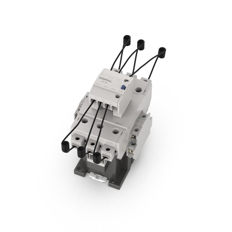
This is why a dedicated capacitor contactor looks different from a standard motor contactor. The resistor circuit, pre-insertion contact arrangement and contact system are specifically designed around capacitor-switching transients. KRIPAL’s UKC1 series uses a pre-insertion mechanism with a pre-charge resistor circuit to limit the inrush current before the main contacts engage.
Reading a Capacitor Contactor Datasheet
This is the part that causes the most confusion in procurement. A capacitor contactor datasheet does not necessarily give you one universal kvar figure. The permissible kvar value can vary with the system voltage, so the correct voltage column must be used for the application.
The reason is that the contactor’s capacitor-switching capability is related to the electrical duty imposed by the capacitor bank. The kvar value is therefore not interchangeable with the general AC-1 or AC-3 current rating.
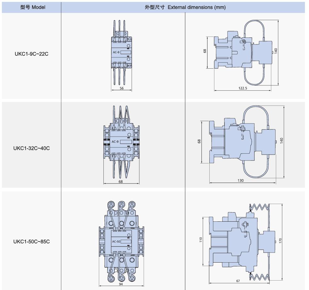
The following is the KRIPAL UKC1 capacitor-switching selection table used for the range:
| Model | kvar at 220 to 240 V | kvar at 400 to 440 V | kvar at 550 to 600 V | Rated current (A) | Delay |
|---|---|---|---|---|---|
| UKC(D)1 to 9C | 5 | 9.7 | 14 | 14 | AC-9 |
| UKC(D)1 to 12C | 6.5 | 12.5 | 18 | 18 | AC-9 |
| UKC(D)1 to 18C | 8.5 | 16.7 | 24 | 24 | AC-9 |
| UKC(D)1 to 22C | 10 | 18 | 26 | 26 | AC-9 |
| UKC(D)1 to 32C | 15 | 25 | 36 | 36 | AC-9 |
| UKC(D)1 to 40C | 20 | 33.3 | 48 | 48 | AC-9 |
| UKC(D)1 to 50C | 22 | 40 | 58 | 58 | AC-50 |
| UKC(D)1 to 65C | 25 | 45.7 | 66 | 66 | AC-50 |
| UKC(D)1 to 75C | 29.7 | 54 | 78 | 78 | AC-50 |
| UKC(D)1 to 85C | 35 | 60 | 92 | 92 | AC-50 |
Important: the kvar value must always be selected from the column corresponding to the actual system voltage. Do not take a kvar figure from one voltage column and apply it to another.
KRIPAL’s current UKC1 product family covers 9A to 85A, with product listings including 50A and 75A capacitor contactors. The manufacturer’s published product information should be used as the final reference when selecting a specific model.
A useful rule is therefore simple: Select the capacitor contactor from the manufacturer’s capacitor-duty kvar table for the actual system voltage, then verify the complete application conditions. Do not reverse-engineer the capacitor-duty rating from the contactor’s general AC-3 current rating alone. The manufacturer’s published capacitor-switching rating is the appropriate starting point for final selection.
Worked Example for a 50 kvar Bank at 400 V
Take an automatic PFC panel with a 50 kvar stage at 400 V, in a plant with some harmonic content from variable-speed drives. Work through the steps in order.
- Step one, calculate the nominal capacitor current.
For a three-phase system: I = Q / (√3 × U)
For a 50 kvar, 400 V stage: I = 50,000 / (1.732 × 400) ≈ 72 A
This is the nominal reactive current at the stated voltage. - Step two, consider the capacitor branch’s permissible continuous current.
Capacitor banks can experience current above their nominal fundamental-frequency current because of voltage variation, capacitance tolerance and harmonic currents. Depending on the applicable capacitor standard and design conditions, a value around 1.3–1.5 times nominal current may need to be considered for the capacitor branch and associated equipment. Manufacturer application data also identifies approximately 1.5 times nominal current as a design consideration for capacitor-switching applications. However, this factor should not be multiplied mechanically against the contactor’s AC-3 rating and then used as a substitute for its capacitor-duty kvar rating. The contactor should be selected using the manufacturer’s dedicated capacitor-switching data. - Step three, select from the kvar column.
For a 400 V system, use the 400–440 V column in the capacitor contactor selection table. Find the model whose published capacitor-switching kvar rating is suitable for the 50 kvar stage. In the KRIPAL selection table above, the UKC(D)1-75C is listed at 54 kvar for 400–440 V, making it a candidate for a 50 kvar stage. Final model selection should be verified against the latest KRIPAL datasheet and the complete switching conditions, particularly where multiple capacitor stages or detuned reactors are involved. - Step four, confirm the switching arrangement.
If this stage can be energized while other capacitor stages are already connected to the bus, the inrush duty can be substantially more severe than for an isolated bank. The contactor’s permissible peak current, switching frequency and the PFC manufacturer’s application requirements should therefore be checked.
If the project uses a detuned reactor, the complete capacitor–reactor assembly should be evaluated rather than selecting the contactor from the capacitor rating alone.
How Detuning Reactors Change the Calculation
Detuned PFC banks add a series reactor, commonly specified at 5.67%, 7% or 14% impedance. The reactor shifts the LC resonant frequency below a selected harmonic order and helps reduce the risk of harmonic resonance between the capacitor bank and the supply network.
For a 50 Hz system, the approximate tuning frequency can be expressed as: fᵣ = f / √p (where p is the reactor impedance percentage expressed as a decimal).
| Detuning factor | Approx. tuning frequency at 50 Hz | Approx. tuning order |
|---|---|---|
| 5.67 percent | About 210 Hz | 4.2nd |
| 7 percent | About 189 Hz | 3.8th |
| 14 percent | About 134 Hz | 2.7th |
The reactor also changes the transient and fundamental-frequency behavior of the capacitor branch. It can substantially alter the inrush current, but the actual transient should be evaluated for the complete capacitor–reactor–network arrangement rather than assumed to fall to a fixed multiple.
The branch current and delivered kvar also need to be considered as part of the complete capacitor–reactor assembly. The reactor’s impedance, capacitor rating, operating voltage and intended kvar output all affect the final design.
In practice, this means the contactor selection must be made for the approved capacitor and reactor assembly rather than for a bare capacitor bank. If the project later adds a reactor, the original contactor selection should be reviewed against the revised branch current, switching transient and manufacturer’s application data.
Switching Frequency and Expected Life
Not all PFC panels switch at the same rate, and the contactor choice should reflect the actual duty cycle rather than only the bank size. A manually switched single bank and a fast-response automatic PFC panel are different applications.
| Application | Typical switching behavior | Selection consideration |
|---|---|---|
| Manual or fixed compensation | Infrequent switching | Select a capacitor-duty contactor matched to the bank and system voltage |
| Automatic PFC with moderate switching | Repeated switching during normal operation | Check electrical endurance and switching frequency |
| Fast response compensation | High switching frequency | Consider the contactor’s maximum switching frequency and whether semiconductor-assisted switching is more appropriate |
Electrical endurance is product-specific. Dedicated capacitor-switching contactors can have substantially different AC-6b endurance values and maximum electrical switching frequencies depending on the design. For example, published manufacturer data can specify hundreds of thousands of AC-6b operating cycles for particular contactor families, but this should never be assumed for every capacitor contactor.
Maintenance intervals should therefore follow the contactor manufacturer’s recommendations and the actual switching duty of the PFC panel. If contact resistance is measured during maintenance, the result should be evaluated against the manufacturer’s specified test method and acceptance limit rather than against a universal value such as 100 microohms.
What to Put in the Purchase Specification
Most selection errors trace back to an incomplete enquiry. If the specification below goes out with the request, the supplier can select a tested device based on the actual capacitor-switching duty rather than guessing from an ampere figure.
- System voltage and frequency, including the highest expected operating voltage.
- Stage kvar and the connection arrangement, delta or star.
- Whether a detuning reactor is fitted, and its impedance percentage if known.
- Number of stages and whether they can be energized while others are already connected.
- Expected operations per day and the minimum off time between reconnections.
- Ambient temperature and enclosure conditions inside the panel.
- Coil supply voltage and type.
- Required auxiliary contacts for indication and interlocking.
- Coordination requirements with upstream fuses or breakers.
- Reference standard and, where relevant, a certificate from a recognized laboratory.
Two of these are worth emphasizing. The maximum operating voltage matters because the capacitor’s reactive current and the switching duty depend on the actual system voltage. A 400 V nominal system should therefore be checked against the applicable voltage range in the contactor’s capacitor-duty table. The minimum off time also matters. A capacitor that has not discharged sufficiently before reclosing can present a significant voltage difference at the instant of switching. This can produce a more severe transient than a fully discharged capacitor bank.
Mistakes That Repeat on Every Project
Several selection mistakes appear repeatedly in capacitor-bank projects:
- Selecting by current rating alone: A contactor with sufficient AC-3 current capacity is not automatically suitable for capacitor switching. Check the manufacturer’s capacitor-duty rating and AC-6b application data.
- Ignoring capacitor inrush current: The nominal kvar current does not represent the transient current at energization. The switching arrangement, source impedance and whether other capacitor stages are already energized can significantly affect the peak current.
- Using generic endurance figures: Do not assume that a contactor rated for a certain number of operations has the same electrical life when switching capacitor banks. Check the published AC-6b electrical endurance and permitted switching frequency.
- Treating all capacitor banks as the same load: A single isolated bank, a multi-stage automatic PFC panel and a bank operating with detuned reactors can impose different switching conditions. Selection should reflect the actual system configuration.
- Ignoring harmonics and detuning reactors: Harmonic distortion can increase capacitor current and electrical stress. Where reactors are used, evaluate the complete capacitor–reactor arrangement rather than applying a generic correction factor.
- Choosing upstream protection without checking coordination: Fuse or circuit-breaker selection should consider the capacitor bank’s continuous current, inrush conditions, fault level and the manufacturer’s coordination recommendations.
- Using an unsuitable reconnection interval: Capacitors can retain voltage after disconnection. The PFC controller and discharge circuit must provide an appropriate reconnection delay so that the capacitor voltage has fallen sufficiently before re-energization.
- Applying motor-contactor specifications to capacitor duty: AC-3 ratings describe motor switching duty and should not be used as a substitute for capacitor-duty data when selecting a contactor for PFC applications.