


 Search
Knowledge Center
Why Standard Contactors Fail on Capacitor Switching
Discover why AC-3 contactors fail on capacitor banks and how AC-6b capacitor switching contactors with pre-charge resistors protect PFC systems.
 June 21, 2026
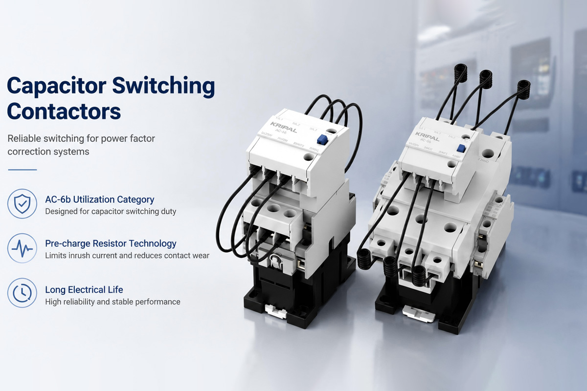
When a discharged capacitor connects to the supply, it appears as a short circuit for the first microseconds. The only limits on the inrush current are the supply transformer impedance, the cable resistance and inductance, and any series reactors in the capacitor bank. In practice, capacitor energization can generate transient inrush currents ranging from several times to more than 100 times the capacitor rated current, depending on system impedance and bank configuration.
A standard AC-3 contactor closes its main contacts directly onto this inrush. The contact tips bounce on closure, generating multiple arcs. Each arc vaporizes a small amount of contact material. After several thousand switching cycles, the silver alloy contact tips erode to the point where the contact gap cannot break the arc during opening. The contacts weld, the capacitor remains connected continuously, and the power factor correction system loses all control.
Capacitor Discharge and Restrike
The capacitor retains its charge after the contactor opens. If the contactor closes again before the capacitor has discharged, the voltage on the capacitor terminals adds to the supply voltage at the moment of closure. This voltage doubling produces inrush currents far exceeding the already high initial inrush. IEC 60831-1 requires built-in discharge resistors that reduce the capacitor terminal voltage to below 75V within three minutes, but rapid switching cycles can occur before full discharge.
How Capacitor Switching Contactors Work
Pre-Charge Resistor Design
A capacitor contactor has early-make auxiliary contacts in series with current-limiting resistors. When the contactor coil energizes, these auxiliary contacts close first, roughly 2 to 5 milliseconds before the main contacts. The capacitor charges through the resistors, limiting the inrush current to a manageable peak. Once the capacitor voltage rises to near line voltage, the main contacts close across a small potential difference, generating minimal arcing.
The resistors in a capacitor contactor are typically wire-wound power resistors with a resistance value calculated to typically reduce the peak inrush current to a controlled level, often around 20–50 times the rated capacitor current. This value represents a compromise between inrush limitation and the resistor power rating during the brief pre-charge period. The resistor must dissipate the energy from every capacitor charge cycle without exceeding its pulse power rating.
The Kripal UKC1 series uses pre-charge resistors and early-make auxiliary contacts to limit capacitor inrush current. The resistors are mounted on the contactor body in a ventilated housing for heat dissipation. The resistor assembly is replaceable as a service part.
Contact Sequencing
The contact sequencing in a capacitor contactor is built into the mechanical design of the contact assembly. The early-make auxiliary contacts are physically positioned to close before the main contacts as the armature travels. On opening, the early-make contacts open after the main contacts so the capacitor remains connected to the resistors during de-energization as well. This prevents the main contacts from breaking the capacitor current at peak voltage.
Sizing a Capacitor Contactor for Your PFC Bank
Kripal UKC1 Capacitor Contactor Selection Table (400V, 50 Hz)
| Capacitor Bank Rating | Rated Current | Required Contactor Rating | Kripal Model | Max Step Size |
|---|---|---|---|---|
| 12.5 kVAR | 18 A | 25 A | UKC1-25C | Single step |
| 16.7 kVAR | 24 A | 32 A | UKC1-32C | Single step |
| 20 kVAR | 29 A | 40 A | UKC1-40C | Single step |
| 25 kVAR | 36 A | 50 A | UKC1-50C | Single step |
| 33 kVAR | 48 A | 63 A | UKC1-63C | Single step |
| 40 kVAR | 58 A | 75 A | UKC1-75C | Single step |
| 50 kVAR | 72 A | 85 A | UKC1-85C | Single step |
Note: Capacitor rated current = kVAR / (√3 × Line voltage). The contactor must be rated for at least 1.3 to 1.5 times the capacitor rated current per IEC 60947-4-1 requirements for AC-6b duty. A standard safety factor of 1.43 has been applied in the table above.
Panel Integration for Capacitor Banks
Physical Layout and Thermal Management
Capacitor banks generate heat. The capacitors produce dielectric losses, the discharge resistors generate continuous heat, and the contactor coils add another heat source. A 100kVAR panel with six capacitor steps can dissipate 300 to 500 watts continuously. Panel ventilation must handle this heat load without exceeding a 40°C internal ambient temperature.
Mount capacitor contactors in the lower section of the panel where air temperatures are lowest. Place the power factor controller in the upper section where its display and buttons are accessible. Route the current transformer signal cable away from the power wiring to avoid induced noise that causes false controller readings.
Adequate clearance should be maintained according to the panel manufacturer’s thermal design requirements. In many applications, 100–150mm airflow space is commonly used. For panels with more than four steps, install a filtered fan in the lower section and an exhaust vent in the upper section. A thermostat-controlled fan prevents continuous operation and extends filter life.
Protection and Fusing
Each capacitor step needs individual overcurrent protection. HRC fuses rated at 1.6 to 2.0 times the capacitor rated current protect against short circuits. The oversizing accounts for capacitor manufacturing tolerance of plus 15 percent on capacitance per IEC 60831-1 and harmonic current drawn by the capacitor from the supply.
A main circuit breaker or fused switch disconnector provides the single isolation point required by IEC 60364 for the entire capacitor bank. The main protection does not replace individual step fusing because a shorted capacitor in one step would otherwise draw fault current through the contactor and busbars of adjacent steps.
Comparing Standard Contactor and Capacitor Contactor
| Characteristic | Standard AC-3 Contactor | Capacitor Switching Contactor |
|---|---|---|
| Utilization category | AC-3 for motor loads | AC-6b for capacitor switching |
| Inrush current handling | 6 times rated current for motor start | Up to 180 times rated current limited by pre-charge resistors |
| Pre-charge mechanism | None, direct main contact closure | Early-make contacts with series resistors |
| Electrical life at rated load | 1 million operations at AC-3 | 200,000 operations at AC-6b |
| Contact material | Silver-cadmium oxide or silver-tin oxide | Silver-tungsten or silver-nickel for arc resistance |
| Typical failure mode | Contact welding from excessive inrush | Contact erosion leading to high resistance |
| Cost comparison | 1× reference | 2× to 3× for equivalent current rating |
Power Factor Controller Integration
A power factor controller measures the system power factor via a current transformer on the main incomer and switches capacitor steps in and out to maintain the target power factor, typically 0.95 to 0.98. The controller outputs are relay contacts rated for the contactor coil current, usually 5A at 250V AC.
The controller logic uses several parameters to decide when to switch each step:
- Target power factor: The desired cos phi value. Setting this above 0.98 risks a leading power factor if the controller overshoots.
- C/K value: The reactive power step size divided by the current transformer ratio. This determines the switching sensitivity. A C/K value set too low causes hunting where steps switch in and out repeatedly.
- Reconnection delay: The minimum time before a discharged capacitor step can be reconnected, typically 40 to 60 seconds. This allows the built-in discharge resistors to reduce the terminal voltage to a safe level.
- Switching interval: A fixed delay between successive step switching, typically 5 to 15 seconds, to avoid rapid consecutive inrush events on the supply.
Harmonics and Detuned Capacitor Banks
Capacitors present a low impedance to harmonic currents. When harmonic distortion exceeds recommended limits (commonly around 5% THDv depending on standards and application), capacitor banks may require detuned reactors. The capacitor bank draws harmonic currents far exceeding the fundamental 50 Hz current rating. This overloads the capacitors and the contactor.
A detuned capacitor bank adds series reactors, typically tuned to 189 Hz for 7 percent detuning, that present a high impedance at harmonic frequencies while remaining capacitive at 50 Hz. The contactor still switches the capacitor-plus-reactor combination, but the reactor limits harmonic loading. Kripal UKC1 capacitor contactors rated 75A and 85A handle detuned banks up to 40kVAR at 7 percent detuning without additional derating.
Browse Capacitor Switching Contactors
Browse Kripal capacitor switching contactors from the UKC1 series, rated 50A to 85A for capacitor banks up to 50kVAR. For technical selection support, contact Kripal engineering with your PFC panel specifications.
Product examples: UKC1 Capacitor Contactor 50A and UKC1 Capacitor Contactor 75A.
Frequently Asked Questions
Q: Can I use a standard contactor for capacitor switching if I oversize it?
Oversizing helps but does not solve the root problem. A standard contactor rated at twice the capacitor current will last longer than one sized to the capacitor current, perhaps tens of thousands of operations instead of a few thousand. But the inrush current is still limited only by the supply impedance, not by the pre-charge resistors found in a capacitor contactor. The contact tips will eventually weld. For automatic PFC banks that switch multiple times daily, the capacitor contactor pays for itself within the first year by eliminating replacement labor and downtime.
Q: How do I know if a capacitor contactor has failed?
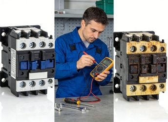
The first sign is the power factor controller calling for a step but the power factor not improving. Check whether the contactor coil is receiving voltage from the controller output. If it is, and the contactor is not closing, the coil may be open. A contactor that has welded closed will keep the capacitor connected continuously, causing leading power factor when the system load is low. The measured reactive power will show a fixed step that does not switch off when the controller output de-energizes. A thermal camera can identify hot spots on the contactor body from excessive contact resistance.
Q: Why do capacitor contactors have a lower electrical life than motor contactors?
Capacitor switching is inherently more aggressive than motor switching. Even with pre-charge resistors, the inrush current peaks are higher than motor starting currents. The capacitive load also creates a different arc behavior during opening. The current leads the voltage by 90 degrees, so the arc extinguishes at a voltage zero crossing but restrikes at the next voltage peak across the opening contacts. Motor contactors break an inductive circuit where the current lags the voltage and the arc is less prone to restrike. The silver-tungsten contacts used in capacitor contactors trade some conductivity for arc erosion resistance that limits the continuous current rating relative to a same-sized motor contactor.
Q: Do I need a separate contactor per capacitor step?
Yes. Each capacitor step in a multi-step PFC bank requires its own contactor because the controller switches steps independently based on the reactive power demand. A six-step bank needs six contactors. The step sizes are often arranged in a binary ratio of 1:1:2:2:2:2 or 1:2:4:8 when using identical capacitor units. This allows the controller to select the combination of steps that most closely matches the reactive power needed. All contactors in the bank should be the same type for common spare parts and consistent switching performance.
Q: Can an AC-3 contactor replace a capacitor contactor?
An AC-3 contactor may operate a capacitor bank temporarily, but it is not designed for repeated capacitor switching. For automatic power factor correction systems, AC-6b capacitor contactors are recommended.
Related Resources
Explore Knowledge Center >
Need a matching KRIPAL product?
Share voltage, quantity and destination. An engineer will reply with options and lead time.
