


 Search
Knowledge Center
How to Install an SPD: Where to Place It and How to Wire It
Learn where to install Type 1, Type 2, and Type 3 SPDs, how to wire them correctly, and why short conductors and backup protection matter.
 July 29, 2026
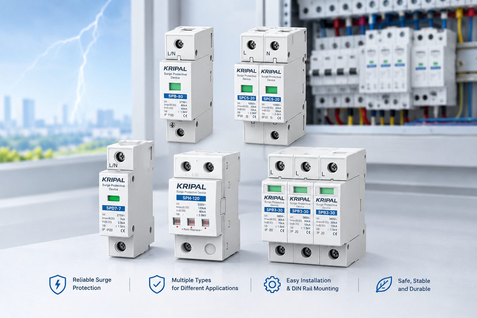
A surge protection device (SPD) can only protect equipment effectively when it is installed in the right location and connected correctly. The most common installation problems are not caused by the SPD itself, but by incorrect placement, excessive conductor length, or unsuitable backup protection. This guide explains where Type 1, Type 2, and Type 3 SPDs are commonly installed, how to wire an SPD correctly, what the 0.5 m connection principle means, and how AC and DC SPDs differ in solar PV systems.
Where Should an SPD Be Installed?
SPD protection is normally arranged in stages. The first stage limits high-energy surges entering an installation, while downstream SPDs reduce the remaining transient voltage closer to sensitive equipment. The exact arrangement depends on the building’s electrical system, lightning protection system, supply configuration, applicable regulations, and coordination between SPDs.
Type 1: The Service Entrance
A Type 1 SPD is used at or near the service entrance where higher-energy lightning currents may enter the electrical installation. It is particularly relevant for buildings with an external lightning protection system or other conditions that increase exposure to lightning currents.
Type 1 SPDs are designed for higher-energy surge currents and are commonly associated with the 10/350 μs test waveform. They provide the first stage of protection rather than replacing downstream surge protection.
Type 2 SPD: Main and Sub-Distribution Boards
Type 2 SPDs are commonly installed in main distribution boards and sub-distribution boards. They help protect downstream circuits against switching surges, induced lightning surges, and residual transient voltages that remain after upstream protection.
For many residential and commercial installations, a Type 2 SPD at the main distribution board is the primary stage of surge protection. Additional Type 2 devices may be required at sub-distribution boards depending on the installation layout and cable lengths.
Type 3 SPD: Near Sensitive Equipment
A Type 3 SPD is normally installed close to sensitive equipment as the final stage of coordinated surge protection. It is suitable for applications involving electronic equipment such as computers, control systems, communication equipment, and other sensitive loads.
Type 3 protection should generally be considered as part of a coordinated system rather than as a replacement for Type 1 or Type 2 protection.
SPD Wiring Rules That Affect Protection
Correct wiring is just as important as selecting the correct SPD. During a fast surge, even a short conductor introduces inductive voltage. As conductor length increases, the additional inductive voltage can increase the voltage that reaches the protected equipment.
Keep SPD Conductors Short
The SPD connection path should be as short and straight as practicable. In installations where the 0.5 m principle applies, the combined length of the relevant SPD connection conductors should generally be kept within 0.5 m, according to the applicable installation standard and the manufacturer’s instructions.
Avoid unnecessary loops, long bends, and routing that creates a large conductor loop. Mounting the SPD close to its connection point is one of the simplest ways to improve its surge-limiting performance.
Minimize Loop Area
SPD conductors should be routed close together and with as little separation and loop area as practicable. The objective is to minimize the inductance of the surge-current path, rather than simply making every conductor exactly the same length.
Always follow the wiring diagram supplied with the specific SPD because the connection arrangement depends on the device design and the electrical system.
Provide Appropriate Backup Protection
An SPD also requires an appropriate backup overcurrent protection arrangement where specified by the manufacturer or applicable installation requirements. This protection limits follow current if the SPD protection element reaches the end of its service life or develops a fault.
The backup device may be a fuse or circuit breaker, depending on the SPD design and system conditions. Its rating should be selected according to the SPD datasheet, short-circuit current, and the manufacturer’s coordination requirements. Built-in thermal disconnection does not automatically eliminate the need to follow the specified backup protection arrangement.
How to Wire an SPD
Before installation, confirm the SPD type, system voltage, maximum continuous operating voltage (Uc), protection level (Up), discharge current ratings, earthing arrangement, conductor requirements, and backup protection.
A typical installation process is:
1
Isolate the electrical installation.
Switch off the relevant supply and verify that the circuit is dead using an appropriate two-pole voltage tester.
2
Mount the SPD correctly.
Install the device on the DIN rail or mounting system specified by the manufacturer, as close as practicable to the connection point.
3
Connect the phase conductors.
Connect the relevant line conductors according to the SPD wiring diagram. Keep the connection path short and avoid unnecessary bends.
4
Connect neutral where required.
For an SPD designed for systems requiring a neutral connection, connect the neutral conductor according to the manufacturer’s diagram.
5
Connect the protective earth.
The PE connection should provide a short, low-impedance path to the earthing system. Avoid unnecessary conductor length and loops.
6
Install the specified backup protection.
Use the fuse or circuit breaker rating specified for the particular SPD and installation.
7
Check the SPD status indicator.
Before commissioning, confirm that the indicator shows the normal operating condition specified by the manufacturer.
8
Energize and verify.
After all connections have been checked, energize the installation and verify the SPD status and system voltage according to the manufacturer’s commissioning procedure.
AC SPD vs DC SPD in Solar PV Systems
Solar PV installations can require coordinated surge protection on both the DC and AC sides of the inverter. The exact number and location of SPDs depend on the system configuration, cable lengths, lightning exposure, risk assessment, applicable standards, and equipment manufacturer’s requirements.
On the DC side, the SPD must be rated for the PV system voltage and installed according to the manufacturer’s requirements. Depending on the installation, protection may be required near the PV array or combiner box and near the inverter’s DC input.
On the AC side, an appropriate AC SPD may be installed at the inverter output and/or the main AC distribution board.
DC and AC SPDs are not interchangeable. A DC circuit does not have the same natural current zero-crossing as an AC circuit, so the SPD must be specifically designed and rated for the DC application.
KRIPAL’s SPC series is designed for DC surge protection applications such as solar PV systems, while the SPB series provides AC surge protection for distribution applications.
Common SPD Installation Mistakes
One of the most common mistakes is using excessively long SPD conductors. Installing the SPD far from the connection point and using long wires can add inductive voltage during a surge and reduce the effectiveness of the protection.
Another mistake is selecting backup protection without checking the SPD manufacturer’s requirements. The correct fuse or circuit breaker rating depends on the specific SPD and the electrical installation.
Installing the wrong SPD type is another common problem. Type 1, Type 2, and Type 3 devices have different applications and performance characteristics. The selection should be based on the installation’s surge exposure, protection concept, and applicable standards rather than simply choosing the lowest-cost device.
For solar installations, another common mistake is considering only one side of the inverter. Depending on the system design and risk assessment, both the DC and AC circuits may require coordinated surge protection.
How to Check an SPD After Installation
Most modern SPDs include a visual status indicator showing whether the protection element is operating normally. Many devices use a green indication for normal operation and a red indication for a fault condition, although the exact indication depends on the product.
If the indicator shows a fault after installation, the installation should not be commissioned until the cause has been identified and the SPD has been confirmed suitable for the system.
Where the SPD provides a remote signaling contact, its status can also be connected to a monitoring or building management system.
Choosing the Right SPD
Choosing an SPD involves more than selecting Type 1, Type 2, or Type 3. Before installation, check the system voltage, Uc, Up, nominal discharge current (In), maximum discharge current (Imax), short-circuit conditions, pole configuration, earthing system, and required backup protection.
For solar PV applications, the DC voltage rating and PV system configuration are especially important. The SPD must be suitable for the maximum continuous voltage present on the DC circuit.
Always compare these parameters with the manufacturer’s technical documentation before selecting and installing the device. Explore KRIPAL’s surge protection device range or the broader circuit protection portfolio when selecting suitable protection devices.
FAQ
How close should an SPD be to the connection point?
SPD conductors should be kept as short and straight as practicable. Where the applicable installation requirements specify the 0.5 m principle, the relevant connection conductors should generally be kept within that total length.
Do I need an MCB or fuse in front of an SPD?
An SPD requires an appropriate backup overcurrent protection arrangement when specified by the manufacturer or applicable installation requirements. The fuse or circuit breaker rating should be selected according to the SPD datasheet and system conditions.
What is the difference between Type 1 and Type 2 SPDs?
Type 1 SPDs are intended for higher-energy lightning-current applications and are commonly associated with the 10/350 μs test waveform. Type 2 SPDs are primarily used at distribution boards to limit transient overvoltages and are commonly tested using the 8/20 μs waveform.
Can I install an SPD myself?
SPD installation involves electrical distribution equipment and should be carried out by a suitably qualified person in accordance with local regulations, applicable standards, and the manufacturer’s installation instructions.
Do solar PV systems need SPDs on both sides of the inverter?
They may. The need for DC and AC surge protection depends on the PV system configuration, cable lengths, lightning exposure, risk assessment, applicable standards, and equipment requirements. The DC and AC SPDs must be correctly rated for their respective circuits.
How do I know if an SPD has failed?
Check the device’s status indicator or remote signaling contact if provided. A fault indication generally means that the SPD protection element requires replacement. The cause of the failure should also be investigated before commissioning the replacement device.
Wire It Right, Once
Effective surge protection depends on both the SPD and the way it is installed. Choose the correct SPD type and electrical ratings, install it at the appropriate point in the protection system, keep the connection conductors short and direct, and follow the specified backup protection requirements.
For AC distribution applications, KRIPAL’s SPB series provides surge protection solutions for suitable installations. For solar PV DC applications, the SPC series is designed for DC-side surge protection.
For product selection, consult the relevant KRIPAL technical documentation and verify the system voltage, SPD ratings, wiring arrangement, and backup protection before installation. Contact KRIPAL for application support.
Related Resources
Explore Knowledge Center >
Need a matching KRIPAL product?
Share voltage, quantity and destination. An engineer will reply with options and lead time.
