


 Search
Knowledge Center
Dry Contact vs Wet Contact: What BMS and PLC Wiring Specs Mean
Compare dry and wet contacts for BMS and PLC wiring: isolation, PNP/NPN, voltage match, and how to wire and test each interface.
 August 04, 2026
The terms dry contact and wet contact appear frequently in BMS, PLC, automation, and electrical control specifications. The basic difference is simple: a dry contact does not provide its own signal voltage, while a wet or powered output provides an electrical signal from the device itself. This distinction affects how a signal is wired, whether the two circuits remain electrically isolated, what voltage the receiving input sees, and whether the PLC or BMS can correctly recognize the signal.
For engineers, technicians, and system integrators, however, the terms should not be considered in isolation. Input voltage, current, polarity, sourcing and sinking logic, and the electrical ratings of the contact or output must also be checked before wiring.
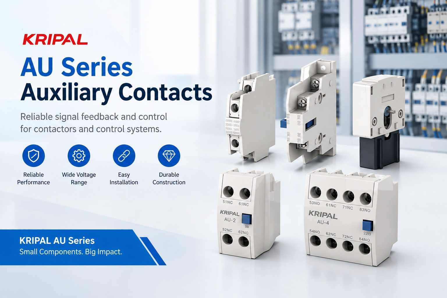
At KRIPAL, we manufacture auxiliary contacts and control components for electrical control systems. This guide explains the practical difference between dry and wet contacts and what these terms mean when reading BMS or PLC wiring specifications.
What Is a Dry Contact?
A dry contact is a switching contact that does not generate its own signal voltage. The external receiving circuit provides the voltage and current, while the contact simply opens or closes the circuit. A mechanical relay contact, contactor auxiliary contact, float switch, and limit switch are common examples. When the contact closes, the voltage supplied by the external circuit can reach the receiving input. When the contact opens, the circuit is interrupted.
For example, a PLC may provide a 24 V DC signal circuit through an auxiliary contact:
Auxiliary contact
PLC input
0 V
The auxiliary contact itself does not produce 24 V DC. It only switches the voltage supplied by the external circuit. Importantly, a dry contact does not mean that the contact can switch any voltage. The actual voltage, current, load type, and AC/DC application must remain within the contact’s rated limits. This is why auxiliary contacts are specified with electrical ratings rather than being treated as completely voltage-independent switches.
Why Is Isolation Important?
A properly isolated dry contact can provide galvanic isolation between two circuits. This allows one device to operate a contact while another device provides the signal voltage. For example, a contactor auxiliary contact can be used to provide a status signal to a PLC or BMS without requiring the contactor’s control circuit to supply the PLC input directly. This type of interface is particularly useful when different devices have separate power supplies or when the system designer wants to keep their power domains electrically independent.
However, a dry contact does not automatically eliminate every possible ground-loop or reference problem. The complete wiring arrangement must be considered, including signal commons, shields, protective earth, and other connections between the equipment.
What Is a Wet or Powered Contact?
A wet contact, also called a powered output in many applications, provides an electrical signal from the device itself. Instead of simply switching an externally supplied circuit, the device’s output is electrically driven and the receiving PLC or BMS input detects that signal.
A common example is a three-wire proximity sensor. The sensor typically has:
- Power supply
- 0 V/common
- Signal output
When the sensor detects an object, its output changes state and provides a signal to the PLC input. The exact behavior depends on the output type. A PNP/sourcing sensor typically drives the signal toward the positive supply voltage, while an NPN/sinking sensor switches the signal toward 0 V. Therefore, it is more accurate to think of a wet contact or powered output as an output that provides or actively switches an electrical signal, rather than simply saying that every wet contact “sends its own voltage.”
Dry Contact vs Wet Contact
| Feature | Dry Contact | Wet / Powered Output |
|---|---|---|
| Signal source | External receiving circuit | Output device |
| Typical examples | Relay, auxiliary contact, switch | Sensor, transistor output |
| Output voltage | Supplied externally | Provided or switched by device |
| Isolation | Can provide galvanic isolation | Depends on output and system design |
| Common applications | Status, interlock, alarm | Sensors, PLC inputs, automation |
| Main checks | Contact voltage/current rating | Input voltage, polarity, output type |
Why the Difference Matters in BMS and PLC Systems
When a BMS or PLC specification says “dry contact input” or “wet contact input,” the wording describes how the signal interface is expected to operate.
The most important questions are:
- Where does the signal voltage come from?
- What voltage and current does the input require?
- Is the input designed for sourcing or sinking operation?
- Are the two circuits required to remain electrically isolated?
- What happens if the signal supply is lost?
These questions are more useful than relying on the words “dry” and “wet” alone. For a dry-contact interface, the receiving circuit normally provides the signal voltage. The contact simply controls whether that voltage reaches the input. For a powered output, the output device provides or actively switches the signal. The receiving input must therefore be compatible with the output voltage, current, polarity, and output type.
Dry Contact vs PNP vs NPN
Dry contact terminology is sometimes confused with PNP and NPN terminology. They describe different aspects of an interface. A dry contact is essentially a switch. PNP and NPN normally describe transistor-based sensor or control outputs.
For example, a PNP sensor typically receives its own power supply and drives its output toward the positive supply when activated. The PLC input must be wired with the appropriate common/reference arrangement. An NPN sensor operates differently by switching the output toward 0 V. This is why a PLC input specification should be checked for sourcing/sinking compatibility, rather than assuming that every three-wire sensor can be connected in the same way.
| Output Type | Basic Function | Typical PLC Application |
|---|---|---|
| Dry contact | Opens/closes an external circuit | Relay or contactor status |
| PNP / sourcing | Drives signal toward +V | PLC input |
| NPN / sinking | Switches signal toward 0 V | PLC input |
| Relay output | Switches an external circuit | Control and status signals |
Voltage Compatibility and Input Requirements
Dry Contact Limits
Voltage compatibility is one of the most common causes of incorrect control wiring. A dry contact can switch the voltage supplied by the receiving circuit, but the contact must remain within its rated electrical limits.
Powered Output Match
A powered output, on the other hand, delivers or switches a specific electrical signal. The receiving input must accept that signal.
For a 24 V DC PLC system, the designer should verify:
- PLC input voltage range
- Input ON/OFF thresholds
- Input current requirements
- Output voltage
- Output current capability
- PNP/NPN or sourcing/sinking arrangement
- DC polarity
- Common/reference connection
Simply seeing “24 V” in both specifications does not guarantee compatibility. The signal level, current, reference, and output configuration must all be suitable for the input.
How to Wire a Dry Contact
A typical dry-contact signal circuit uses an external supply:
Dry contact
PLC/BMS input
Circuit common
The contact does not supply the voltage. It only completes or interrupts the circuit.
Before wiring, check the contact’s:
- Rated voltage
- Rated current
- AC/DC switching capability
- Load type
- Electrical endurance
For a contactor auxiliary contact used for status feedback, for example, the PLC or BMS can provide the monitoring voltage through the auxiliary contact. When the contactor changes state, the auxiliary contact changes state and the receiving system detects the corresponding input condition.
How to Wire a Wet or Powered Output
A powered output is connected according to the output and input design.
For a typical three-wire sensor, the connections may include:
- Power supply → sensor
- 0 V/common → sensor and input reference
- Signal output → PLC input
However, the exact wiring depends on whether the sensor output is PNP/sourcing or NPN/sinking.
Before connecting a powered output, confirm:
- PLC/BMS input voltage range
- Sensor/output voltage
- Output type
- Common/reference requirements
- DC polarity
- Maximum output current
- Input current requirements
Never assume that a powered output can be connected directly to any PLC input simply because the connector or terminal arrangement looks similar.
What Happens When the Wrong Interface Is Used?
One of the most common mistakes is confusing a dry contact interface with a powered input or output. If a powered output is connected to an input that expects an isolated dry contact, the external voltage may be applied where it is not expected. Depending on the equipment design, this can result in an incorrect signal or, in the worst case, damage.
The opposite mistake can also cause problems. If an input expects a powered signal but receives only a dry contact without an appropriate external supply, the input may never reach its required ON threshold.
The correct approach is simple:
Do not determine compatibility from the words “dry” or “wet” alone.
How to Test a Dry or Wet Contact
A dry mechanical contact can normally be checked with a continuity or resistance measurement, with the circuit safely isolated before testing. When the contact is closed, the measured resistance should typically be very low. When open, the meter should indicate an open circuit. A powered output is normally checked by measuring the signal voltage under the appropriate operating conditions.
For DC systems, polarity and the reference/common connection should also be considered.
Always follow the equipment manufacturer’s safety and testing procedures before making measurements on energized circuits.
FAQ
What is the difference between a dry and wet contact?
A dry contact is a switching contact that does not provide its own signal voltage. The receiving circuit supplies the voltage. A wet or powered output provides or actively switches an electrical signal from the output device.
Is a relay output a dry contact?
A mechanical relay output is normally treated as a dry contact output because its contacts do not generate the signal voltage. The external circuit provides the voltage that the relay contacts switch.
Can a dry contact be used with a PLC?
Yes. A dry contact can be used with a PLC input when the input circuit, voltage, current, and contact ratings are compatible. The PLC or an external supply normally provides the signal voltage.
What is the difference between PNP and NPN?
PNP is commonly associated with sourcing an output toward the positive supply, while NPN is commonly associated with sinking the output toward 0 V. The PLC input must be wired for the corresponding output configuration.
Why do BMS specifications often use dry contacts?
Dry contacts are useful when the interface needs the two circuits to remain electrically independent. A properly isolated contact can transfer a status or control signal without directly connecting the power supplies of the two devices.
How do I test a dry contact?
For a mechanical dry contact, use a continuity or resistance test with the circuit safely isolated. For a powered output, measure the signal voltage and verify it against the equipment specification.
What voltage rating do KRIPAL auxiliary contacts have?
The exact voltage, current, insulation, and utilization ratings depend on the specific KRIPAL auxiliary contact model. Always confirm the applicable values in the product datasheet before selecting or wiring the component.
Dry Contact or Wet Contact: Choose by the Interface, Not the Name
The basic difference is straightforward: a dry contact switches an externally supplied circuit, while a wet or powered output provides or actively switches an electrical signal. For BMS and PLC applications, however, reliable wiring requires more than identifying the contact type. Voltage range, current, polarity, galvanic isolation, sourcing/sinking logic, and PLC input requirements must all be considered.
For contactor status feedback, interlocking, and control circuits, KRIPAL AU Series auxiliary contacts provide dry-contact interfaces for applications within their specified electrical ratings.
For exact voltage, current, and utilization ratings, refer to the applicable product datasheet or contact the KRIPAL engineering team for application guidance. Browse related contactors and relays for compatible control components.
Related Resources
Explore Knowledge Center >

Need a matching KRIPAL product?
Share voltage, quantity and destination. An engineer will reply with options and lead time.
