



Knowledge Center
How to Design DC Protection for a Megawatt Charging Hub (MCS)
Complete guide to Megawatt Charging System (MCS) protection: AC/DC distribution, 1250V DC bus fault handling, bay isolation, surge mitigation, and thermal derating.
 August 25, 2026
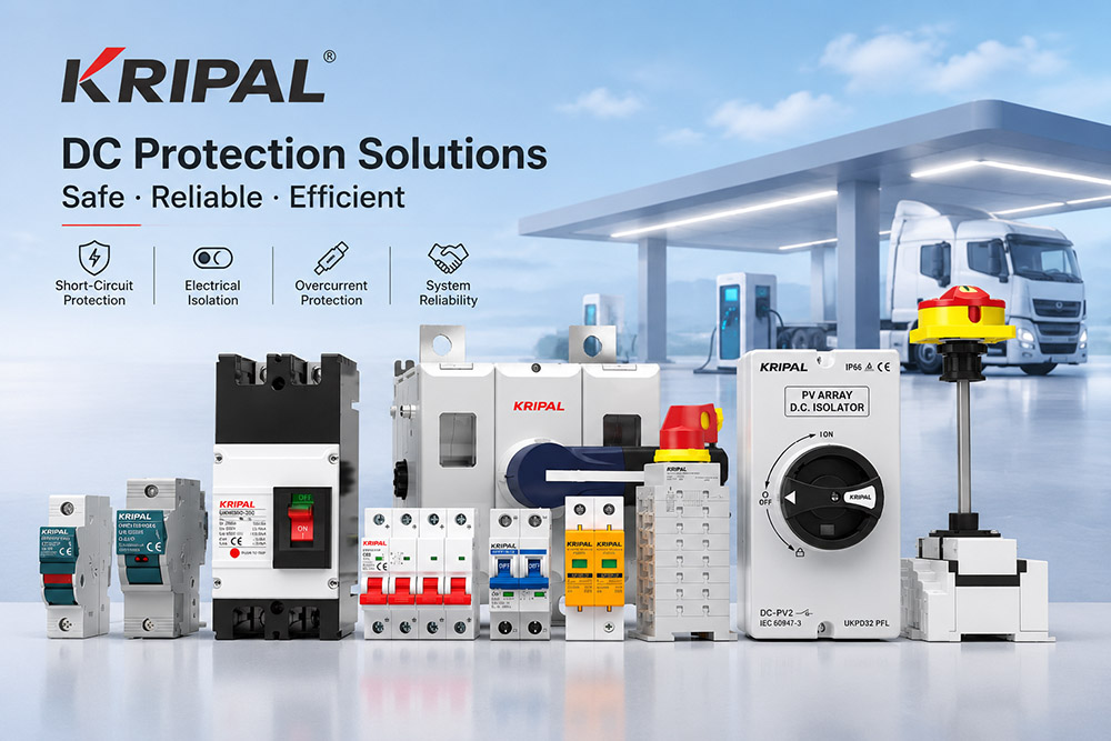
MCS Megawatt Charging System brings new challenges for heavy-duty electric vehicle charging infrastructure, especially for high-voltage DC protection. Proper protection design covers AC distribution, DC-bus fault handling, bay-level isolation, surge mitigation, and thermal derating, rather than only picking individual components. This article walks through system-level protection best practices for Megawatt Charging Hubs, and how KRIPAL DC-rated switching & protection components support your MCS project.
Megawatt Charging System (MCS) technology is transforming heavy-duty electric vehicle charging. With charging power reaching the megawatt range, electrical protection becomes more than a matter of selecting suitably rated circuit breakers. It requires coordinated design across AC distribution, DC bus protection, charging bay isolation, fault current analysis, surge protection, and thermal management.
An MCS charging hub may contain several high-power charging bays supplied by a common electrical infrastructure. Each bay introduces different operating conditions, switching requirements, and potential fault paths. The protection system must therefore be designed around the complete electrical architecture rather than individual devices alone.
CharIN’s MCS technical specifications define a maximum DC voltage of 1,250 V and continuous current capability of up to 3,000 A. At the maximum voltage and current combination, the theoretical charging power reaches 3.75 MW. Actual charging power depends on the capabilities of the vehicle and charging equipment. In North America, SAE J3271 addresses MCS requirements, while IEC 61851-233:2026 specifically covers DC electric vehicle supply equipment for megawatt charging systems.
This guide explains the main protection considerations when designing an MCS charging hub, from the incoming AC supply to individual DC charging bays.
Site Distribution Architecture
A megawatt charging hub can be divided into four main electrical zones: the AC supply and transformer, the rectifier and DC conversion stage, the DC distribution bus, and the vehicle interface. Each zone has different electrical characteristics and fault conditions, so protection must be coordinated across the complete system.
The AC side follows established industrial power distribution principles. The DC side requires additional attention because DC fault interruption, stored capacitor energy, converter behavior, possible reverse-current paths, and circuit time-constant (L/R) create different protection challenges. Surge protective devices (SPD) shall be implemented both on the AC incoming side and the main DC-link bus to mitigate switching transients and lightning-induced overvoltages for power converters and downstream charging bays.
AC Supply and Transformer
The transformer and AC switchgear are selected according to the charging hub’s maximum operating demand, utility connection conditions, and available short-circuit current.
A multi-bay charging station can place a substantial demand on the local electrical network. Transformer capacity, impedance, cable sizing, switchgear ratings, power quality, and surge protection must therefore be evaluated during the initial design stage.
Power electronic converters may introduce harmonic currents into the supply network. Depending on the rectifier topology and operating conditions, these harmonics can affect transformer heating, cable losses, and protective device performance. Transformer specifications and AC protection settings should account for the actual converter characteristics and expected loading profile.
Rectifier Output Bus
The rectifier converts incoming AC power into DC power for the charging system. Its output feeds the DC distribution bus, which supplies individual charging bays.
Prospective DC fault current cannot be determined from the rectifier’s rated output current alone. The calculation must consider the complete fault path, circuit L/R time-constant, and all relevant energy sources. DC interrupting performance of breakers and fuses is heavily dependent on the system L/R value, which shall be cross-checked against manufacturer device test data.
Rectifier and DC/DC converter fault-current output.
Energy stored in DC-link capacitors.
Connected battery systems, where the topology permits reverse current flow.
Other connected energy storage equipment.
Vehicle batteries should not automatically be treated as fault-current sources in every MCS installation. Their contribution depends on converter design, vehicle-side contactors, isolation arrangements, and operating conditions.
The protection study should identify each possible current path and establish the magnitude and duration of fault current at relevant locations. DC circuit breakers and fuses must then be selected according to the actual prospective fault conditions and their verified DC ratings.
For DC short-circuit applications in MCS infrastructure, gR or gPV type fuses are commonly specified for fast semiconductor and DC-bus protection.
Bay Isolation
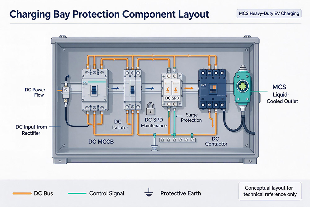
Each charging bay should have a dedicated isolation arrangement and appropriately coordinated short-circuit protection. This helps limit the impact of a fault in one bay and allows maintenance without unnecessarily shutting down the entire hub.
The isolator provides electrical isolation. Its rated voltage, operating current, pole configuration, and short-time withstand capability must be suitable for the installation.
Short-circuit interruption should be assigned to a DC-rated circuit breaker or fuse system designed for the prospective fault current at that location. Where a switch-disconnector or fuse-switch combination is used, its certified making capacity and conditional short-circuit rating must also be verified.
An isolator should not be assumed to have the same short-circuit interruption capability as a circuit breaker.
Vehicle Interface and BackFeed
The vehicle interface introduces another important consideration: the possibility of reverse current flow from the vehicle battery into the charging equipment. MCS supports bidirectional power transfer as part of its broader technical development. However, this does not mean every connected vehicle automatically contributes battery fault current to a common DC bus.
The actual current path depends on the charging equipment architecture, converter design, vehicle-side contactors, and electrical isolation arrangements. Insulation monitoring devices (IMD) are mandatory for 1,250 V DC vehicle interfaces to detect gradual insulation degradation before earth faults occur.
The isolation strategy should define how the charging cable, vehicle interface, DC output stage, and distribution bus are separated under normal shutdown, emergency shutdown, and fault conditions.
| Electrical Zone | Main Protection Requirements |
|---|---|
| AC supply and transformer | Coordinated AC switchgear and overcurrent protection; AC-side SPD for surge mitigation |
| Rectifier output | DC-rated short-circuit protection; DC-bus SPD; gR/gPV fuse options |
| DC distribution bus | Coordinated DC breakers or fuses; consider circuit L/R time-constant |
| Charging bay | Individual feeder protection and safe isolation |
| Vehicle interface | Controlled shutdown, electrical isolation, and insulation monitoring (IMD) |
Bay Isolator Rating Requirements
Selecting a bay isolator based only on its rated operating current is insufficient. The device must also be suitable for the system voltage, pole arrangement, installation conditions, and short-circuit withstand requirements.
At DC voltages approaching 1,250 V, interruption is particularly demanding because DC current does not have the periodic natural zero crossings found in AC systems. The device must have an appropriate DC arc-extinguishing design and verified ratings for its intended application.
When selecting a DC isolator, engineers should check:
Rated operational voltage (Ue) and current (Ie).
Number of poles and approved series-pole connection.
Short-time withstand current, where applicable.
Short-circuit making capacity, where specified.
Conditional short-circuit rating with the specified upstream protective device.
Installation polarity and connection requirements.
Connecting multiple poles in series does not automatically establish a higher DC voltage rating unless the manufacturer has tested and approved that configuration.
IEC 60947-3 covers switches, disconnectors, switch-disconnectors, and fuse-combination units. The applicable product category and certified ratings must be checked for the specific installation.
Making and Breaking Capacity of DC Switching Devices
DC contactors and circuit breakers perform different functions and should not be treated as interchangeable. A DC contactor is primarily used to establish and interrupt controlled operating current. Selection should consider rated operational voltage, current, utilization category, electrical endurance, and specified making and breaking duties.
A contactor may also need to withstand prospective short-circuit current until an upstream fuse or circuit breaker clears the fault. This requires proper coordination between the contactor and the short-circuit protective device.
A standard contactor should not be treated as a substitute for a DC-rated circuit breaker or fuse. Engineers should verify manufacturer test data for the actual DC voltage, current, circuit time constant (L/R), polarity, and switching arrangement.
Consequences of Closing onto a Fault
Closing a switching device onto an existing short circuit can produce severe electrical and mechanical stress. Depending on device design and fault conditions, the consequences may include contact welding, excessive arc energy, internal pressure, and damage to contact systems or arc-extinguishing chambers. This is why making capacity, breaking capacity, and short-circuit withstand capability must be evaluated separately where applicable.
The upstream protective device must clear the fault within the required time. Downstream contactors and switching equipment must withstand the resulting electrical stress until the fault is interrupted. Protection coordination should be verified using manufacturer test data and the actual prospective short-circuit current, rather than relying only on nominal current ratings.
Utilization Category and Operations per Day
A charging bay may experience repeated connection, charging, shutdown, and disconnection cycles. Switching equipment must therefore be selected according to its actual operating duty.
Selecting a contactor only by its thermal current rating can result in insufficient electrical endurance, particularly where the device frequently switches high operating currents.
The specification should include:
Expected switching operations per hour and per day.
Rated operating voltage and current.
Actual load characteristics and utilization category.
Electrical endurance under specified operating conditions.
Expected service life and maintenance interval.
Electrical endurance must be checked against the actual DC switching duty, not inferred from thermal current alone. AC motor contactor ratings should not automatically be considered suitable for high-voltage DC charging circuits.
Cable, Cooling and the Thermal Design
At current levels approaching 3,000 A, liquid-cooled charging cables are an important design consideration. The required cooling arrangement depends on rated current, operating duty, ambient temperature, cable construction, and connector thermal limits.
Cable bend radius, connector weight, coolant routing, and cooling equipment location all affect the charging bay layout. Inside the electrical cabinet, protection devices may be installed close to rectifiers, converters, and high-current busbars. The internal temperature can therefore be considerably higher than the outdoor ambient temperature.
Thermal Derating in the Cabinet
The rated current of an electrical device is determined under specified reference conditions. When the actual operating temperature exceeds those conditions, correction or derating may be required. For example, a device selected using a 40 °C reference ambient temperature may not maintain the same permissible operating current when installed in a cabinet operating at 55 °C.
The amount of derating depends on the product and installation conditions. Engineers should use the manufacturer’s published temperature correction curves and consider cabinet ventilation, heat dissipation, busbar temperature rise, component spacing, and nearby converter losses.
Coolant Leakage as an Electrical Hazard
A coolant leak does not automatically create an earth fault. However, if conductive coolant reaches energized components or compromises insulation, it can cause insulation deterioration, earth faults, or short circuits. The design should include suitable separation between coolant pipes and live DC components, leak detection where required, and defined shutdown and interlocking responses.
Coolant lines should be routed away from DC busbars wherever possible. Leak detection should be integrated with the charging control system so that the affected bay can enter a defined safe state without unnecessarily shutting down the entire hub.
Utility Capacity and Protection Assumptions
A charging hub with six 3.75 MW bays has a combined nameplate charging capacity of 22.5 MW if all bays operate at maximum rated power simultaneously. In practice, the utility connection may provide a lower available power capacity. An energy management system can therefore limit simultaneous charging demand and distribute available power among connected vehicles.
However, load management must not be confused with short-circuit protection. Limiting normal operating power does not automatically limit prospective short-circuit current at every point in the installation.
Equipment ratings and protection settings should be based on the actual electrical network model and verified fault calculations, not simply on contracted power capacity or the sum of charging bay nameplates.
Commissioning Sequence
Commissioning should verify that the installed protection system performs according to the approved electrical design and manufacturer instructions.
A practical commissioning sequence should include:
Confirm that every DC switching and protection device is suitable for the maximum system voltage and approved series-pole arrangement.
Confirm that relevant fault-current sources, DC-link energy, L/R parameters, converter characteristics, SPD performance, and possible vehicle-side current paths have been considered.
Check that each charging bay can be safely isolated and that remaining electrical sections enter the intended safe state.
Verify coordination between contactors, circuit breakers, isolation devices, and emergency shutdown circuits.
Verify insulation monitoring (IMD), protective conductor continuity, and earth-fault protection according to the system design.
Confirm that DC fuses (gR/gPV type where applicable) and circuit breakers have suitable ratings and that downstream equipment can withstand fault conditions until interruption.
Compare operating temperatures with the assumptions used in thermal and derating calculations.
Where fuses provide DC short-circuit protection, selection must consider rated voltage, current, breaking capacity, time-current characteristics, and total clearing I²t. Downstream contactors, cables, and busbars must withstand the associated thermal and electrodynamic stress until the fuse interrupts the fault.
Lead Time Planning
Protection devices used in a megawatt charging hub require careful engineering coordination. High-voltage DC circuit breakers, contactors, isolators, and other switching equipment must be selected according to system voltage, current, fault level, and L/R operating duty.
Some high-power DC devices may require project-specific verification, special configurations, or longer procurement lead times. Enclosure and busbar designs may also depend on equipment dimensions, connection arrangements, clearances, and thermal performance.
Protection selection should therefore begin during the electrical design stage rather than being postponed until the charging connectors and mechanical layout are finalized.
A complete equipment specification should include rated parameters, applicable standards, certification requirements, fault ratings, installation conditions, and delivery schedules.
Project Considerations
Megawatt charging is fundamentally a power distribution and protection challenge, not simply a connector upgrade. The connector determines how energy is transferred to the vehicle, but system safety and reliability depend on the complete electrical architecture.
Engineers should define protection zones, identify possible fault-current sources, calculate prospective fault current together with L/R values at relevant locations, and select devices according to verified DC operating and short-circuit ratings.
How KRIPAL Supports DC Protection Applications
KRIPAL provides low-voltage electrical protection and switching products, including DC circuit breakers, DC isolator switches, fuse holders, and contactors for applications within their specified ratings. These products support DC distribution, electrical isolation, and protection coordination in industrial and renewable energy installations.
Note: For full-scale 3,000 A continuous-current MCS bay requirements, multipole paralleling configuration will be required as part of system design to reach the high continuous-current target, as individual unit ratings do not directly cover the maximum MCS full current.
For EV charging and other high-power DC projects, device selection must be verified against actual system voltage, current, prospective fault level, circuit L/R time-constant, pole configuration, and applicable certification requirements. KRIPAL works with customers to identify suitable electrical protection components based on project specifications and product capabilities.
For project-specific requirements, contact the KRIPAL team to discuss DC protection components, technical specifications, and product selection.
Frequently Asked Questions
What is the maximum power of an MCS charging system?
MCS supports up to 1,250 V DC and 3,000 A continuous current capability. At the maximum voltage and current combination, theoretical charging power reaches 3.75 MW.
Why is DC protection more challenging than AC protection?
DC current does not have the periodic natural zero crossings found in AC systems. This makes arc interruption more demanding, particularly at high voltages and currents. DC fault performance is also heavily influenced by circuit L/R time-constant.
Can a standard AC circuit breaker be used in an MCS DC system?
No. A circuit breaker must have verified DC operating and short-circuit ratings suitable for the installation, including voltage, current, L/R capability, and pole configuration.
Does every connected electric truck feed fault current back into the DC bus?
No. Vehicle battery backfeed depends on the electrical topology, converter design, vehicle-side contactors, and isolation arrangements.
What is the difference between a DC isolator and a DC circuit breaker?
A DC isolator provides electrical isolation for maintenance and safety. A DC circuit breaker is designed to interrupt specified overload and short-circuit currents. Their functions and ratings should not be confused.
How should a DC contactor be selected for an MCS application?
Selection should consider rated voltage, current, utilization category, making and breaking duties, electrical endurance, circuit L/R conditions, and actual DC circuit conditions. The contactor must also be coordinated with an upstream DC fuse or circuit breaker.
Why is thermal management important in megawatt charging systems?
High charging currents generate heat in cables, connectors, busbars, and switching devices. Liquid cooling, cabinet ventilation, and appropriate device derating help maintain safe operating temperatures.
Which protection devices are used in DC charging infrastructure?
Depending on the system architecture, DC charging infrastructure may use DC circuit breakers, fuses (gR/gPV), isolators, surge protective devices (SPD), insulation monitoring devices (IMD), and associated control and interlocking equipment.
Need component-selection support for your MCS megawatt charging hub or high-power DC charging project? Reach out to the KRIPAL engineering team for technical consultation and component recommendations.
Disclaimer
This article provides general technical guidance only and shall not substitute project-specific engineering work, including short-circuit studies, fault-current calculations, L/R time-constant evaluations, and local regulatory compliance assessments per IEC, SAE J3271, and site-applicable standards.
All component selections must be fully verified against actual site conditions, official manufacturer datasheets, and certification documents. KRIPAL accepts no liability for any consequences arising from direct application of this general guidance without independent professional engineering validation.
Related Resources
Explore Knowledge Center >
Need a matching KRIPAL product?
Share voltage, quantity and destination. An engineer will reply with options and lead time.
