


 Search
Knowledge Center
Cable Entry and Sealing for Outdoor Electrical Enclosures
Prevent water ingress in outdoor electrical enclosures. Learn how to select cable glands, seal unused entries, and maintain IP66 ratings with KRIPAL.
 August 08, 2026
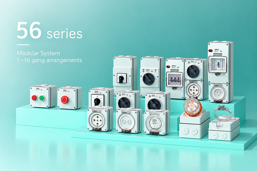
An outdoor electrical enclosure is rated as a complete assembly, but cable entries are often one of the first places where its protection can be compromised. An enclosure specified as IP66, for example, cannot maintain the same level of protection if the cable gland is incorrectly selected, an entry is poorly prepared, or an unused opening is left unsealed.
Cable entry design therefore involves more than choosing an enclosure with a high IP rating. Cable diameter, gland selection, entry position, wall penetration, sealing components, cable routing and installation all affect the final result.
This guide explains the main causes of water ingress, how to select and install cable entries, and how to maintain the intended protection level of outdoor electrical enclosures.
Why Cable Entry Sealing Matters
Water can enter an outdoor enclosure through several paths. The enclosure lid is only one of them. Cable entries, unused openings and wall penetrations can also become potential routes for water ingress if they are not correctly sealed.
Water Can Travel Along the Cable
A cable installed outdoors can carry water toward an enclosure, particularly when the cable approaches the entry from above. Rainwater can run along the cable sheath and reach the gland.
For this reason, cable routing and entry position should be considered together with the enclosure itself. Where practical, downward-facing cable entries and a suitable drip loop can help reduce the amount of water reaching the entry point.
A bottom entry can also reduce exposure to water running down an enclosure wall, although it does not eliminate the need for a correctly selected and installed cable gland.
How Cable Glands Seal an Enclosure
The enclosure wall itself does not normally provide the seal around the cable. A cable gland is designed to secure the cable and create a seal around its outer sheath.
A hole in an enclosure without an appropriate gland, blanking plug or other approved sealing method is simply an opening.
When selecting a cable gland, consider:
- The actual outer diameter of the cable
- The gland’s specified cable diameter range
- The entry thread or mounting interface
- The required IP protection level
- The enclosure material and wall thickness
- The manufacturer’s installation instructions
The cable gland should be suitable for the required protection level of the installation. The IP rating of the gland alone does not guarantee the same rating for the completed enclosure; the complete installation and all interfaces must be suitable.
Cable Diameter vs. Conductor Cross-Section
One of the most common selection mistakes is confusing conductor cross-section with cable diameter. Conductor cross-section is normally expressed in mm² and is relevant to the electrical terminal and conductor capacity. Cable glands, however, are normally selected according to the outer diameter of the complete cable. Two cables with the same conductor cross-section can have different outside diameters because of differences in the number of cores, insulation and sheath construction. For this reason, measure the actual cable diameter before selecting the gland.
Sealing Components
Depending on the gland design, components may include a sealing element, locknut, sealing washer or other interface components. Their position and installation method vary by product.
Always install these components according to the cable gland manufacturer’s instructions. A correctly tightened gland with an incorrectly positioned sealing component may still compromise the enclosure’s protection.
Unused Cable Entries Must Be Sealed
Unused entry positions are another common source of water ingress. If an enclosure has more cable entry positions than the installation requires, unused openings should be closed with suitable blanking plugs or other approved sealing components. A blanking plug should be correctly selected and tightened according to the manufacturer’s instructions. Simply leaving an opening unused does not preserve the enclosure’s IP protection.
Preparing Knockouts
Where a knockout is provided, remove the knockout material completely before installing the gland. The remaining edge should be free from sharp burrs that could damage the cable gland seal or cable sheath. If necessary, carefully remove burrs using an appropriate tool. The objective is to create a clean mounting surface without damaging the enclosure or its sealing surfaces.
Matching the Cable Gland to the Cable
Correct gland selection begins with the actual cable rather than the enclosure opening alone.
Check the cable’s:
- Outer diameter
- Number of cores
- Construction
- Minimum bending radius
- Installation environment
Then compare the measured cable diameter with the manufacturer’s specified gland range. Do not select a gland simply because its thread fits the enclosure. A gland can have the correct thread while still being unsuitable for the cable diameter. Likewise, when two gland sizes appear suitable, follow the manufacturer’s specified cable diameter range and installation requirements rather than assuming that the smaller or tighter gland is automatically better.
KRIPAL Outdoor Isolating Switches: Cable and Product Specifications
Cable entry selection also needs to take the electrical device into account. The terminal system and the cable gland must both be suitable for the cable being installed.
KRIPAL 56SW outdoor isolating switches are available in different configurations and current ratings. The published product information should be used to confirm the applicable cable and terminal specifications for each model.
| Model | Configuration | Published cable range | Protection |
| 56SW310 | 3 pole, 10 A, 500 V | 1.5–16 mm² | IP66 |
| 56SW320 | 3 pole, 20 A, 500 V | 2.5–16 mm² | IP66 |
| 56SW350 | 3 pole, 50 A, 500 V | 10–25 mm² | IP66 |
| 56SW463 | 4 pole, 63 A, 500 V | 16–25 mm² | IP66 |
The values above describe the published cable range associated with the relevant product. They should not be treated as cable gland diameter ranges. The actual gland must still be selected according to the outside diameter of the complete cable and the gland manufacturer’s specifications.
View the full KRIPAL 56SW outdoor isolating switch range
Wall Penetrations, Cable Routing and Drip Loops
Cable entries through walls introduce another boundary that needs to be considered. Where a cable passes through an external wall into an enclosure, the penetration should be designed so that water is not directed toward the enclosure interior. Where appropriate for the installation, a slight fall toward the outside can help prevent water from collecting at the penetration. Cable routing should also respect the cable manufacturer’s minimum bending radius. Excessive bending close to a gland can place mechanical stress on the cable sheath and gland.
Separate the Wall Penetration From the Gland
The wall penetration and the cable gland perform different functions. The penetration must be appropriately sealed and protected, while the gland provides the cable entry and sealing interface at the enclosure. Treating these as separate installation points helps prevent one of them from being overlooked. Where additional sealant is required, use a material compatible with the cable sheath, enclosure and environmental conditions. A permanently flexible sealant may be appropriate where movement and thermal expansion need to be accommodated, but the sealant manufacturer’s instructions should always be followed.
Choosing Outdoor Junction Boxes and IP Ratings
When the enclosure is being used to make electrical joints rather than simply house a device, the type of junction box also affects the installation.
A box with a factory-fitted terminal block can simplify wiring and reduce the number of separate components required inside the enclosure. A box supplied without terminals provides more flexibility but requires the electrical joint to be correctly made inside the enclosure.
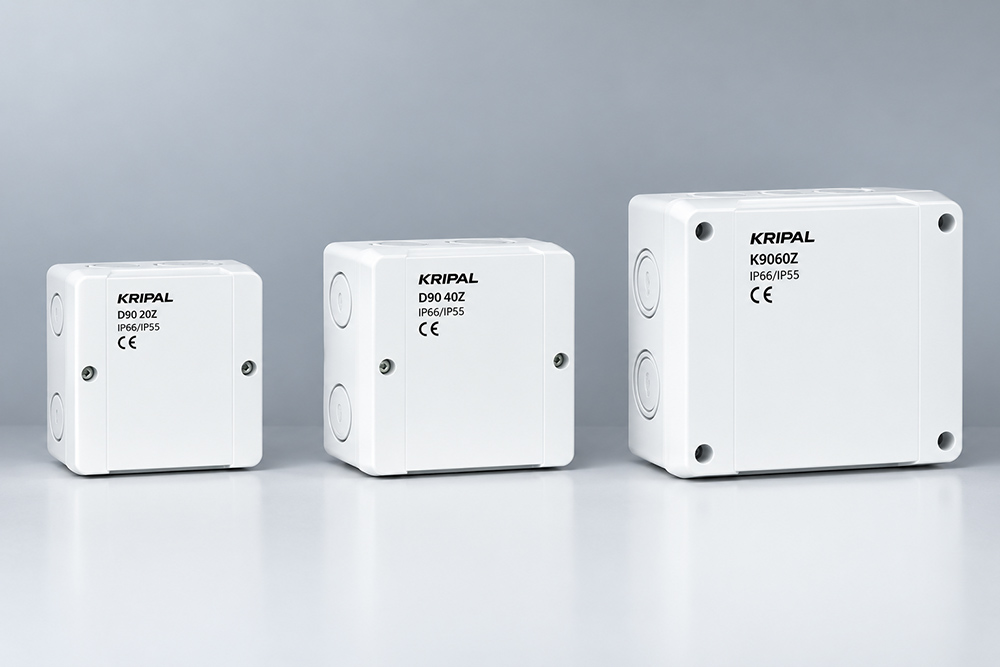
KRIPAL outdoor wall-mounted junction boxes are available in different configurations, including versions with and without terminals and different protection levels.
For example, the published range includes IP54 and IP65 versions, with sizes ranging from approximately 88 × 88 mm to 200 × 160 mm. The appropriate IP rating should be selected according to the actual installation environment, exposure to water and dust, installation method and applicable project requirements. A higher IP number should not be treated as a substitute for correct installation.
Explore the KRIPAL outdoor junction box range
When the Gland Must Be Angled
Some installations require a cable to enter through the top or side of a larger enclosure. If the cable cannot maintain its required bending radius, an angled gland or suitable cable-entry accessory may be necessary. The objective is to avoid excessive bending or pulling forces at the entry point. The cable should never be forced into a bend tighter than its specified minimum bending radius. Mechanical stress can damage the cable sheath and place additional load on the gland.
Sealing Materials and Environmental Conditions
Sealing components have their own service life. Heat, ultraviolet exposure, chemicals, vibration and repeated temperature changes can affect sealing materials over time. The enclosure body, lid gasket, cable gland seal and blanking plug may use different materials and therefore age at different rates.
What to Check During Maintenance
| Part | Main factors | What to check |
| Enclosure body | UV exposure, impact | Cracks, damage or surface deterioration |
| Lid gasket | Heat, chemicals, ageing | Flexibility and deformation |
| Cable gland seal | Cable diameter, movement, ageing | Compression, hardening and distortion |
| Blanking plug | Vibration, temperature cycling | Tightness and seal condition |
| Wall penetration | Cable movement, environmental exposure | Seal condition and cable support |
Chemical exposure should also be considered. Cleaning agents or other chemicals may affect sealing materials, depending on their composition. Where an enclosure is installed in a demanding environment, the compatibility of the sealing materials should be checked against the manufacturer’s specifications.
Installation Inspection Checklist
A visual inspection alone cannot confirm that an enclosure will maintain its intended protection during service. Before commissioning an outdoor installation, check the main entry points carefully.
Cable Entry Checklist
- Confirm the gland is suitable for the actual outer cable diameter.
- Confirm the gland thread or mounting interface matches the enclosure.
- Check that the required sealing components are correctly installed.
- Confirm every unused entry is closed with an appropriate blanking plug.
- Check that knockout edges are clean and free from damaging burrs.
- Check that the cable is not bent tighter than its specified minimum radius.
- Inspect wall penetrations and confirm that water is not directed toward the enclosure.
- Check that the enclosure lid gasket and other sealing surfaces are correctly seated.
- Verify that the completed installation meets the required protection level.
Keeping the IP Rating After Installation
The IP rating published for an enclosure describes its tested configuration under specified conditions. Once cables are installed, drilled openings are created and accessories are fitted, the installation must still be completed correctly to achieve the required protection.
Every cable entry, gland, blanking plug and penetration is therefore part of the final installation.
One useful practice is to determine the cable diameter and select the appropriate gland before drilling the enclosure. This reduces the risk of creating an entry that does not match the selected gland.
For a specific KRIPAL installation, the cable type and diameter, enclosure position and number of entries can be provided to the technical team for product and accessory selection.
Contact: sale3@kripal.com
Tel: +86 15381576159
Frequently Asked Questions
The IP rating applies to the enclosure and its tested configuration. Water ingress can occur when cable glands are incorrectly selected or installed, unused openings are not properly sealed, sealing components are missing or damaged, or cable and wall penetrations are poorly prepared.
Not necessarily in the same configuration for every gland. The required sealing washer, locknut and other components depend on the specific gland design. Always follow the installation instructions supplied with the cable gland.
The sealant must be compatible with the cable, enclosure and environmental conditions. Where cable movement and temperature changes are expected, a suitable permanently flexible sealant may be preferable to a rigid material. Always follow the sealant manufacturer’s application and compatibility requirements.
Conclusion
Maintaining the IP protection of an outdoor electrical enclosure depends on more than the enclosure itself. Cable diameter, gland selection, unused openings, wall penetrations, cable routing, sealing materials and installation quality all contribute to the final result.
The most practical starting point is to measure the actual cable diameter, select a compatible cable gland, prepare each enclosure entry correctly and inspect every unused opening before commissioning.
For outdoor isolating switches, junction boxes and other electrical enclosures, matching the product specifications with the actual installation environment is equally important. KRIPAL’s outdoor product range provides different enclosure and switching configurations for outdoor electrical applications, while the final installation should always follow the relevant product documentation and applicable requirements.
Related Resources
Explore Knowledge Center >
Need a matching KRIPAL product?
Share voltage, quantity and destination. An engineer will reply with options and lead time.
