



Knowledge Center
Mechanical Support of DC Busbars and Short-Circuit Forces
Master DC busbar short-circuit electrodynamic force calculations, square-law dynamics, mechanical support spacing, and DC MCCB terminal withstand standards.
 August 21, 2026

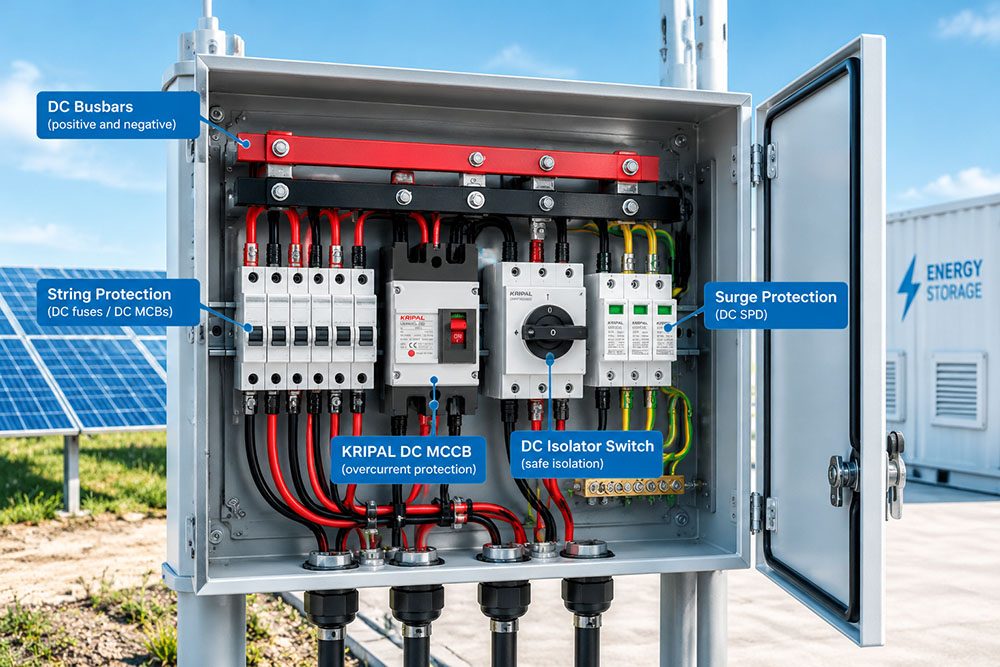
A busbar carries its normal operating current with relatively little mechanical movement. During a short circuit, however, the magnetic fields produced by the fault current can create substantial electrodynamic forces between conductors and on their supports. For a simplified pair of parallel conductors, the force increases with the product of the instantaneous currents and decreases as the distance between conductor centers increases.
This guide explains the source of these forces, the inputs needed for a preliminary estimate, and the mechanical details that must be checked in a DC busbar assembly. Battery connections, inverter connections, and combiner-box wiring can all be critical locations, but the available fault current depends on the source characteristics, system topology, circuit impedance, and protective devices. The method described here is an engineering overview, not a substitute for a project-specific short-circuit withstand assessment. For an overview of DC protection and isolation products used in solar and energy storage systems, explore KRIPAL’s solar DC electrical components.
Where the Force Comes From
The force between current-carrying conductors is caused by their magnetic fields. Parallel conductors carrying current in the same direction attract one another; conductors carrying current in opposite directions repel. In a DC circuit, the supply and return conductors commonly carry current in opposite directions, although the actual force on each bar depends on the complete conductor arrangement and current distribution.
The Square Law
For two ideal, long, parallel conductors carrying equal current in opposite directions, the magnitude of the force per unit length is proportional to the square of the current and inversely proportional to the center-to-center spacing. Consequently, doubling the current can increase the force by a factor of four when the other assumptions remain unchanged. A busbar assembly connected to a source with a higher prospective fault current may therefore experience forces well beyond those considered during normal-current sizing.
The force also depends on conductor spacing and geometry. Closely spaced conductors generally experience a greater magnetic interaction than otherwise comparable conductors placed farther apart. However, spacing is only one design variable; conductor dimensions, orientation, supports, fault-current waveform, and the surrounding conductors must also be considered.
Why Direct Current Is Different
The instantaneous electrodynamic force depends on the instantaneous currents and their relative directions. In an AC fault, the current waveform varies and may pass through zero; when the currents in both conductors reverse together, the force between them does not necessarily reverse direction. In a DC fault, current generally does not alternate in direction, but its magnitude can rise rapidly after fault initiation and then decrease or be interrupted by the protective device.
It is therefore not sufficient to assume that DC produces a constant force or that an AC design is automatically more or less robust. Mechanical design should use the relevant peak current, fault duration, conductor arrangement, and protective-device characteristics for the actual system.
Estimating the Force
A preliminary estimate needs the relevant current values, conductor geometry, and spacing. For an ideal pair of long, parallel conductors, a simplified force-per-unit-length relationship is:
Here, F/L is the force per unit length, I₁ and I₂ are the instantaneous currents in the two conductors, d is the center-to-center spacing, and μ₀ is the permeability of free space. If the current magnitudes are equal, the magnitude becomes F/L = 2 × 10⁻⁷ I²/d in SI units (N/m), for this simplified geometry.
This expression provides a preliminary estimate for an idealized pair of long, straight, parallel conductors. The current values should represent the relevant instantaneous currents for the condition being assessed, and the spacing is measured between conductor centers. The equation does not, by itself, establish the short-circuit mechanical withstand of a complete busbar assembly.
For an actual installation, the assessment should consider the conductor arrangement, peak fault current and waveform, support spacing, busbar cross-section and orientation, fixing conditions, and the mechanical strength of supports, fasteners, and connections. Where protective devices limit the fault current, verified manufacturer data may be needed to establish the relevant peak current. Use an applicable engineering calculation method and verify the complete assembly against the project requirements.
Inputs That Are Often Wrong
The peak fault current is not the rated current of the device, and it should not automatically be equated with the prospective short-circuit current. The peak depends on source voltage and characteristics, circuit resistance and inductance, connection topology, and any current-limiting protective device. In a battery system, battery internal resistance and the number and arrangement of parallel strings are important inputs, but they are not the only factors.
Establish the design current from a documented short-circuit calculation, verified manufacturer data, or an appropriate validated test method. Do not conduct an uncontrolled short-circuit test on a high-energy battery system simply to obtain a measurement.
For a pair of bars, spacing in the simplified formula is measured center to center, not as the clear air gap. Parallel length is the length over which the conductors run alongside one another; it is not the same as the distance between mechanical supports. Support spacing is a separate structural input.
| Input | What It Means | Common Error |
|---|---|---|
| Peak fault current | Maximum instantaneous current relevant to the mechanical assessment | Using rated current or assuming it equals prospective short-circuit current |
| Conductor spacing | Center-to-center distance in the simplified parallel-conductor model | Using the clear gap between bars |
| Parallel length | Length over which conductors run alongside one another | Confusing it with support spacing |
| Support spacing | Distance between mechanical supports | Selecting it from panel layout without a mechanical check |
| Force direction | Attraction or repulsion resulting from current directions and geometry | Assuming the direction without checking the arrangement |
Supporting a Busbar
Mechanical support may be provided by insulators, the enclosure structure, or a combination of both. The arrangement determines how electrodynamic loads are transferred through the busbars, supports, fasteners, and enclosure. The assessment should consider not only the busbar stress and deflection but also the strength of the supports, mounting points, and connections.
Reducing the Span
For a simple beam under a uniform distributed load, the maximum bending moment varies with the square of the unsupported span. For example, a simply supported beam with a uniform load has Mmax = wL²/8. Under those assumptions, halving the span reduces the maximum bending moment to one quarter. Actual busbar systems may have different load distributions, support stiffness, and end restraints, so this relationship should not be used as a stand-alone rating rule.
Adding an intermediate support can reduce the unsupported span, but each support and its fixing arrangement must be rated for the load it will carry. The final spacing should come from the mechanical assessment and applicable product or assembly requirements, not from a general rule of thumb.
Section and Orientation
A busbar’s resistance to bending depends on its cross-section and orientation. A flat bar has different stiffness and section modulus about its two principal axes. Where the installation allows, orienting the bar so that the relevant fault force acts in the stiffer bending direction can improve mechanical performance, but the complete arrangement still needs verification.
In assemblies with multiple parallel bars, the resultant force on each conductor depends on the current distribution, relative current directions, spacing, and overall geometry. Do not assume that all adjacent forces simply add on the outermost bar. Assess the combined forces acting on each bar and its supports using the actual layout.
Restraint at the Terminals
Breaker terminals are electrical connection points and should not be treated as structural supports unless the manufacturer explicitly permits the intended mechanical loading. A rigid busbar connection can transfer bending loads to a terminal block. A suitably designed flexible link, such as a laminated shunt or a short cable connection, can reduce the transfer of bending loads and accommodate some thermal expansion or assembly tolerance.
A flexible link does not eliminate all mechanical loads. Its current rating, temperature rise, short-circuit withstand, routing, bend radius, and terminal compatibility must be suitable for the application. The busbar, flexible link, and supports should be assessed as one connected assembly.
Checks Before Energising a DC Busbar
The following checks complement the electrical commissioning checks. They should be completed by competent personnel before the system is energized and should be supported by design calculations and manufacturer documentation where required:
Confirm the calculated prospective fault current at the busbar using verified source data, circuit impedance, and the system configuration.
Confirm the peak current used in the mechanical assessment and document how it was established.
Check support spacing against the calculated mechanical loads, not only the panel layout.
Verify the mechanical ratings and fixing arrangements of intermediate supports, insulators, and fasteners.
Check that busbar orientation and spacing match the assessed conductor arrangement.
Confirm that breaker terminals are not exposed to unapproved structural loads and that any flexible links are correctly specified.
Verify that the busbars, supports, connections, and enclosure have suitable mechanical withstand for the relevant fault conditions.
Busbar Device Specifications
DC circuit breakers and isolators have defined electrical ratings and terminal arrangements, but these ratings do not automatically establish the mechanical withstand of the external busbar system. Busbar support design remains an assembly-level responsibility. The device’s rated short-circuit breaking capacity describes its ability to interrupt a fault under specified conditions; it does not, by itself, determine the peak electrodynamic force acting on the busbars.
For a DC moulded-case circuit breaker, confirm the rated operational voltage, pole configuration, breaking-capacity rating, installation conditions, and the manufacturer’s coordination or current-limitation data. Where the device limits current, verified peak let-through data may be relevant to the mechanical calculation. Do not infer the actual peak force from the frame rating or breaking-capacity figure alone. For product-specific ratings and available configurations, see KRIPAL’s DC molded case circuit breakers for solar PV and battery storage systems.
For a DC isolator, verify the rated operational voltage, utilization category, rated making and breaking characteristics, conductor arrangement, and the conditions under which the published values apply. Making and breaking ratings are not interchangeable with prospective fault current or peak let-through current. Confirm all product figures against the current official datasheet for the exact model before publication or design use. For model-specific DC isolation options, refer to KRIPAL’s DC isolator switches for solar PV applications.
How protective devices in a battery or DC distribution system coordinate with each other is covered in the related guide on selective coordination in electrical distribution.
Frequently Asked Questions
Can I use AC busbar mechanical design rules directly for DC busbar short-circuit assessment?
No. In AC short-circuit events, the fault current alternates direction, yet the electrodynamic force does not always reverse. For DC faults, the fault-current magnitude rises rapidly while the current direction stays unchanged. Always perform mechanical verification using DC-specific peak fault currents, fault durations, and conductor layouts instead of simply reusing AC design experience.
What is the difference between prospective short-circuit current and peak let-through current for DC busbar calculation?
Prospective short-circuit current is the theoretical maximum fault current without current-limiting effects. Peak let-through current is the real-world maximum instantaneous current that passes through a current-limiting protective device during a fault. For mechanical busbar strength checks, you must use the verified peak let-through value rather than the prospective short-circuit current.
Why cannot a circuit breaker short-circuit breaking rating be used to judge whether my DC busbar assembly can withstand short-circuit forces?
The rated short-circuit breaking capacity defines a protective device’s ability to interrupt and clear a fault under designated conditions. It does not represent the actual peak electrodynamic force acting on external busbars, insulators, and structural fasteners. Busbar mechanical withstand is an assembly-level design task independent of the breaker’s internal electrical breaking performance.
When calculating short-circuit force between two parallel DC busbars, should I input the air gap distance or center-to-center distance?
The simplified parallel-conductor force formula requires the center-to-center spacing between conductors. The clear air gap between bars is not the correct input parameter and will deliver incorrect force estimation results.
Is it acceptable to treat circuit breaker terminals as mechanical support points for rigid DC busbars?
Generally not, unless the component manufacturer explicitly permits specified mechanical loads on terminals. Rigid busbars may transfer severe bending stress onto breaker terminals. Laminated flexible shunts or short flexible links are recommended to mitigate bending loads, though flexible links themselves also require short-circuit and thermal validation.
Does doubling the DC fault current double the short-circuit electrodynamic force on busbars?
No. Short-circuit force follows a square-law relationship with current. If other conditions remain unchanged, doubling the fault current will quadruple the electrodynamic force, which is why peak fault current is the single most critical input for mechanical assessment.
Conclusion
A DC busbar is both an electrical conductor and a mechanical component. Its short-circuit withstand depends on the peak fault current, conductor geometry, support spacing, cross-section, fixing arrangement, and the behavior of protective devices. Start with documented fault-current data, estimate the electrodynamic loads using an appropriate method, and then verify the busbars, supports, fasteners, and terminal connections as a complete assembly.
The most common design mistake is to use a convenient current value without confirming that it represents the peak relevant to the mechanical assessment. Prospective short-circuit current, peak current, and current limited by a protective device are fundamentally different quantities.
Related Resources
Explore Knowledge Center >

Need a matching KRIPAL product?
Share voltage, quantity and destination. An engineer will reply with options and lead time.
