


 Search
Knowledge Center
Contactor Coil Voltage Drop: Calculation, Causes and Solutions
Learn how long control cables cause contactor coil voltage drop and chatter. Discover how to calculate voltage drop and select the right coil voltage.
 August 10, 2026
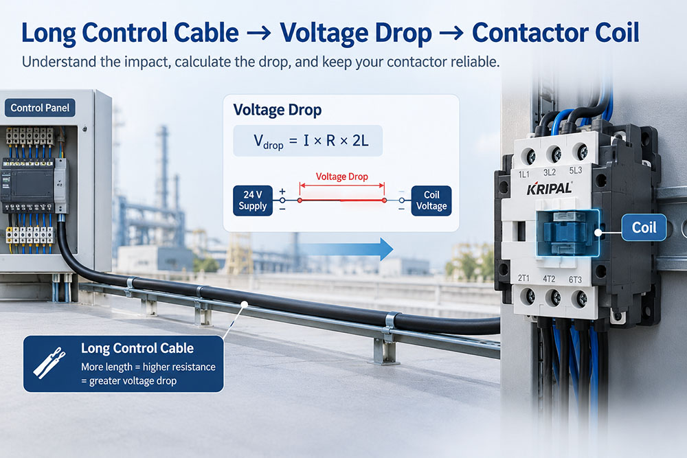
A contactor coil is an electrical load, and a long control cable adds resistance between the control supply and the coil. As cable length increases, the voltage available at the coil can decrease, particularly when the coil draws higher current during pull-in. If the voltage at the coil falls outside its specified operating range, the contactor may fail to pull in reliably or may chatter during operation.
This guide explains how control-circuit voltage drop affects contactor coils, how to calculate the drop on a long cable run, how to diagnose contactor chatter, and how to select a suitable control voltage and conductor size.
Why Is a Contactor Coil Sensitive to Voltage?
A contactor coil must generate enough magnetic force to move the armature against the mechanical spring and close the main contacts. The required force depends on the magnetic circuit and the current through the coil. When the voltage available at the coil is too low, the coil may not generate sufficient force to complete the pull-in operation. A contactor may therefore fail to close, pull in slowly, or pull in and then release again.
This is one reason the same contactor can operate normally in one installation but chatter or fail to pull in in another installation with a longer control cable. The actual acceptable coil voltage depends on the contactor design and the manufacturer’s specified operating range. The rated coil voltage alone should not be used as the only acceptance criterion.
Pull-In Current vs. Holding Current
For many conventional AC contactors, the coil current is significantly higher during pull-in than after the armature has closed. When the armature is open, the magnetic circuit has a larger air gap and higher reluctance. Once the armature closes, the magnetic circuit becomes more efficient and the coil’s steady-state current can decrease. This difference is important when a contactor is controlled through a long cable. The higher current during pull-in creates a larger voltage drop in the control conductors. If that voltage drop reduces the coil voltage below the required operating range, the contactor may fail to complete the closing operation.
A contactor can also chatter when it repeatedly pulls in and releases. The control voltage falls under the higher pull-in current, the contactor loses sufficient holding force, and the cycle repeats.
How a Long Control Cable Causes Voltage Drop
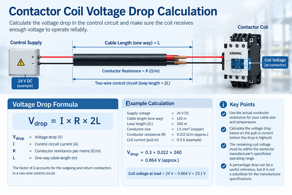
Every conductor has electrical resistance. For a given conductor material and temperature, resistance increases with length and decreases as conductor cross-sectional area increases. In a typical two-wire control circuit, current travels from the control supply to the contactor coil and returns through the second conductor. The voltage drop therefore depends on the total loop length rather than only the one-way distance.
For a simplified two-wire circuit:
Or:
Where:
- Vdrop = voltage drop in volts
- I = circuit current in amperes
- R = conductor resistance per meter
- L = one-way cable length in meters
The resistance value should be selected for the conductor size and, where appropriate, the expected operating temperature. Copper resistance increases as conductor temperature rises, so using a resistance value appropriate to the installation conditions gives a more realistic result. The longer the cable and the higher the current, the greater the voltage drop.
This is particularly important during contactor pull-in, when the coil current may be higher than during the holding condition.
How to Evaluate Contactor Coil Voltage Drop
The calculated voltage drop should not simply be compared with the rated coil voltage as an isolated number.
The important question is: Will the voltage remaining at the coil stay within the contactor manufacturer’s specified operating range under the worst-case operating condition?
For example:
If a 24 V control supply experiences a 3 V drop, approximately 21 V remains at the coil under that particular load condition. Whether 21 V is acceptable depends on the specific contactor’s coil operating requirements. A percentage-based voltage-drop target can be useful during preliminary control-circuit design, but it should not replace the manufacturer’s specified coil operating limits. The pull-in condition should receive particular attention because it can represent the highest current demand.
Measuring the voltage directly at the coil terminals while the contactor is operating is one of the most useful ways to verify the actual condition in the field.
Why Low-Voltage Coils Are More Sensitive
For coils with similar power requirements, a lower-voltage coil generally draws more current than a higher-voltage coil. The relationship can be simplified as:
Therefore, for a similar power requirement, reducing the operating voltage increases current. Higher current produces greater voltage drop in the same conductor. At the same time, a given voltage drop represents a larger percentage of a low-voltage supply.
For example, a 5 V drop represents approximately:
| Coil Supply | 5 V Drop |
| 24 V | 20.8% |
| 110 V | 4.5% |
| 220 V | 2.3% |
| 380 V | 1.3% |
This table illustrates why long control-cable runs can be more challenging for low-voltage control circuits. However, the table is only a comparison of the percentage drop. It does not establish whether a particular contactor coil will operate correctly. The final check must be made against the actual coil operating range specified for the selected contactor.
Choosing the Right Contactor Coil Voltage
Coil voltage should be selected based on the available control supply, control-system requirements, safety considerations and cable installation conditions. Where a long cable run creates excessive voltage drop, using a higher coil voltage may reduce the current required for a similar coil power level and can therefore reduce voltage-drop problems. However, selecting the highest available coil voltage is not automatically the correct solution.
The selected coil must be compatible with:
- The available control supply
- PLC or control-device output requirements
- Safety requirements
- Control-circuit architecture
- Applicable electrical standards
- The contactor manufacturer’s coil specifications
KRIPAL contactors are available with different coil-voltage configurations depending on the product series and model. The exact coil voltage should therefore be selected from the relevant product specification rather than assumed from the contactor frame size. For long-distance control circuits, the engineering objective is to ensure that sufficient voltage remains at the coil during the most demanding operating condition.
When 24 V Control Is Required
24 V control circuits are widely used where lower control voltage is preferred for operator interfaces, automation systems or specific safety applications. A 24 V control circuit can work reliably over a long distance, but conductor selection becomes more important as the cable length increases.
If the calculated voltage drop is too high, possible solutions include:
- Increasing conductor cross-sectional area
- Reducing cable length
- Reducing the current carried by the long control circuit
- Relocating the control device
- Using an interposing relay
- Reviewing the selected coil voltage where the control system permits
The correct solution depends on the complete control-circuit design rather than on cable length alone.
Using an Interposing Relay for Long Control Runs
An interposing relay can be useful when the contactor is located a significant distance from the main control panel. The relay can be installed closer to the contactor so that the long cable carries the relay’s control current rather than the contactor’s higher pull-in current. The contactor coil can then be supplied locally through a shorter connection. This arrangement can reduce the voltage-drop problem without changing the contactor’s coil voltage.
An interposing relay also adds another component and therefore another potential failure point, so it should be used where the overall control-system design justifies it. For installations with several contactors located in remote panels, local control arrangements can be a practical way to reduce long high-current control paths.
How to Diagnose Contactor Chatter
Contactor chatter should not automatically be attributed to a defective contactor. A voltage measurement at the coil terminals can quickly determine whether the control circuit is supplying the required voltage.
Use the following checks:
- Measure the voltage at the contactor coil terminals while the contactor is energized.
- Compare it with the control voltage measured at the source end of the same circuit.
- Calculate or measure the voltage drop across the control conductors.
- Check whether other control loads are energized at the same time.
- Confirm that the installed conductor size matches the electrical drawing or design specification.
- Inspect terminals and connections at both ends of the control circuit for looseness, corrosion or other connection problems.
- Check the contactor coil and control circuit against the manufacturer’s specifications before replacing the contactor.
For AC contactors, a simple resistance measurement of the coil with a multimeter should not be treated as a complete test of coil performance. The more useful field measurement for a suspected voltage-drop problem is normally the actual coil voltage under load.
Testing the Control Circuit Before Commissioning
Control-circuit voltage drop can often be identified before the contactor is placed into service.
Continuity and Conductor Resistance
With the circuit safely isolated, the resistance of the conductors can be checked and compared with the expected value based on conductor size and cable length.
A significant difference may indicate:
- An incorrect conductor size
- An unexpectedly long cable route
- A poor connection
- A damaged conductor
- An incorrect installation
The resistance measurement should be interpreted according to the test method, conductor temperature and circuit configuration.
Voltage Under Load
The most meaningful voltage-drop check is performed while current is flowing. A voltage measurement taken with the contactor disconnected does not show the voltage drop caused by the loaded control circuit.
Measure:
The difference between the source voltage and the voltage measured at the coil represents the voltage lost in the control path under that operating condition. Where several contactors share the same control supply, test them both individually and under simultaneous operating conditions. A circuit that works correctly with one contactor energized may experience additional voltage drop when multiple loads operate at the same time.
Worked Example: A 24 V Contactor Over a 120 m Cable
Consider a control circuit using a 24 V supply with a contactor located 120 meters from the control panel. The conductor size is 1.5 mm² and the circuit uses a two-wire control path.
The electrical loop length is therefore:
The voltage drop is calculated from:
The actual result depends on the conductor resistance and the contactor’s current during the relevant operating condition. If the voltage drop is large enough to reduce the voltage at the coil below its specified operating range during pull-in, the contactor may fail to close reliably or may chatter.
Several solutions can then be considered:
- Increase the conductor size
- Reduce the cable length
- Use a suitable higher-voltage coil if permitted by the control system
- Relocate the control or contactor
- Use an interposing relay to reduce the current carried over the long control cable
The key point is that cable length should be evaluated together with coil current and conductor resistance. Cable length alone does not determine whether a contactor will operate reliably.
KRIPAL Contactors and Thermal Overload Relays
KRIPAL offers industrial control products for applications where reliable contactor operation and motor protection are required. For a contactor application, the selected model should be matched to the motor or load, control voltage and control-circuit requirements.
Where motor overload protection is required, a compatible thermal overload relay can be selected according to the motor’s rated current and the applicable contactor combination.
The exact coil voltage, current range, auxiliary-contact configuration and overload-relay setting range should always be confirmed from the relevant KRIPAL product datasheet before ordering.
This approach keeps the technical selection tied to the actual application rather than selecting a contactor based only on its frame size.
Conclusion
Long control cables can create significant voltage drop, particularly when they carry the higher current associated with contactor pull-in. The correct approach is to consider the coil current, conductor resistance, cable length and available control voltage together. Calculate the voltage drop using the complete circuit path, then verify that the resulting voltage at the contactor coil remains within the manufacturer’s specified operating range.
Related Resources
Explore Knowledge Center >

Need a matching KRIPAL product?
Share voltage, quantity and destination. An engineer will reply with options and lead time.
