BESS DC Protection Guide
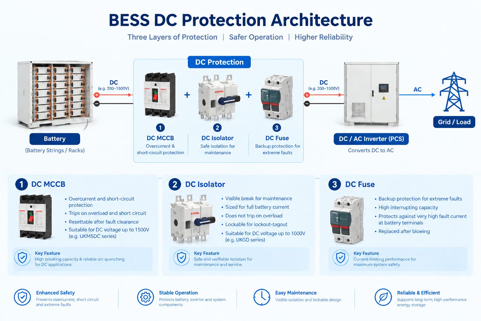
Battery energy storage systems (BESS) can deliver substantial DC fault current, so protection must be selected for the actual DC voltage, continuous current, and prospective fault conditions of the installation. A typical BESS protection architecture may combine overcurrent protection, a dedicated disconnecting or isolation device, and supplementary or backup protection such as a fuse. The exact combination depends on the battery architecture, PCS/inverter design, available fault current, applicable installation requirements, and the ratings of the selected devices.
What DC Protection Does a BESS Need?
These devices do not perform the same function. A breaker is primarily an overcurrent protection device, an isolator is primarily for safe disconnection, and a fuse may provide additional or backup protection. A complete design should not assume that every BESS requires the same three-device arrangement.
| Device |
Primary function |
Typical role |
| DC MCCB |
Overload and short-circuit protection |
Interrupts faults within its rated breaking capability and can normally be reset after a cleared fault. |
| DC isolator / disconnect |
Safe and verifiable isolation |
Provides a dedicated means of disconnecting the circuit for maintenance; lockability may be required by the installation procedure. |
| DC fuse |
Overcurrent and backup/current-limiting protection |
Can provide supplementary or backup protection where its voltage, current, and interrupting ratings are suitable. |
Why BESS DC Protection Is Different From AC Protection
The key difference is the behavior of the interruption arc. AC current passes through a natural zero crossing, which can help an AC-rated switching device extinguish an arc. A DC circuit does not have that periodic zero crossing, so a device interrupting DC must be specifically designed and rated for the DC voltage and interruption conditions.
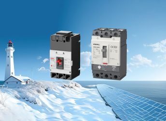
For this reason, an AC-only breaker should not be assumed to be suitable for a battery circuit. A breaker may be used on DC only when its manufacturer provides an appropriate DC rating for the voltage, current, pole configuration, and application. For AC distribution projects, KRIPAL also provides circuit breakers, but BESS DC selection must be verified separately.
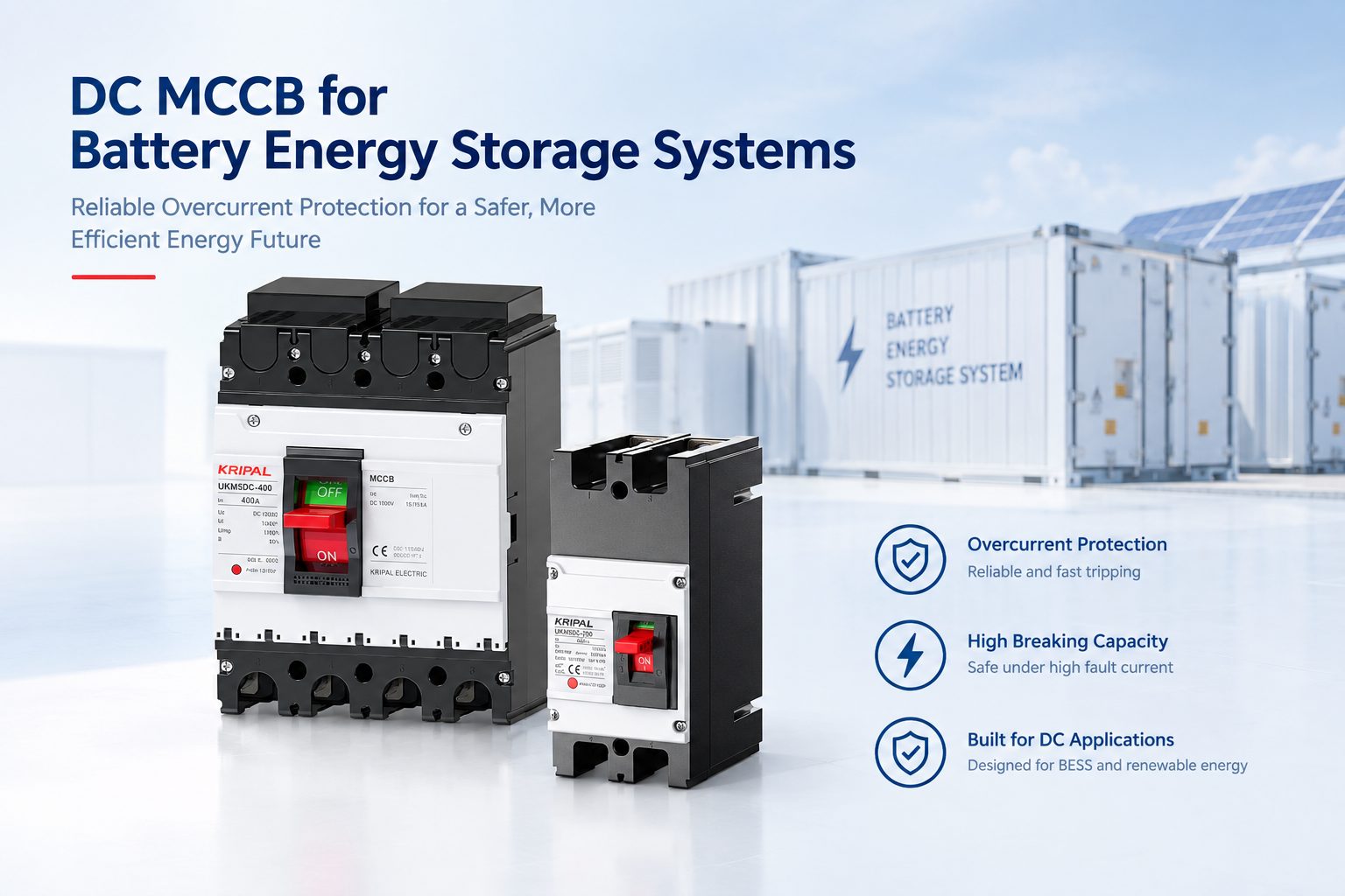
Selecting a DC MCCB for BESS
The DC MCCB is normally selected from several independent parameters rather than from nominal battery voltage and current alone.
- DC voltage rating: The device rating should meet or exceed the maximum operating and charging voltage of the system.
- Continuous current rating: Select the device according to the maximum continuous operating current, conductor ampacity, environmental conditions, applicable installation requirements, and the manufacturer’s ratings.
- Interrupting or breaking rating: The MCCB’s DC interrupting capability must be suitable for the prospective fault current at its installation point.
- Trip characteristics: The overload and short-circuit characteristics should be appropriate for the battery/PCS circuit and coordinated with downstream and upstream protection.
- Pole configuration and DC switching arrangement: Follow the manufacturer’s application instructions for the system voltage and circuit configuration.
- Derating and environmental conditions: Temperature, enclosure conditions, and installation method can affect the usable current rating.
For related molded case breaker applications, review KRIPAL’s MCCB product information and confirm DC suitability from the actual datasheet.
Selecting a DC Isolator for BESS
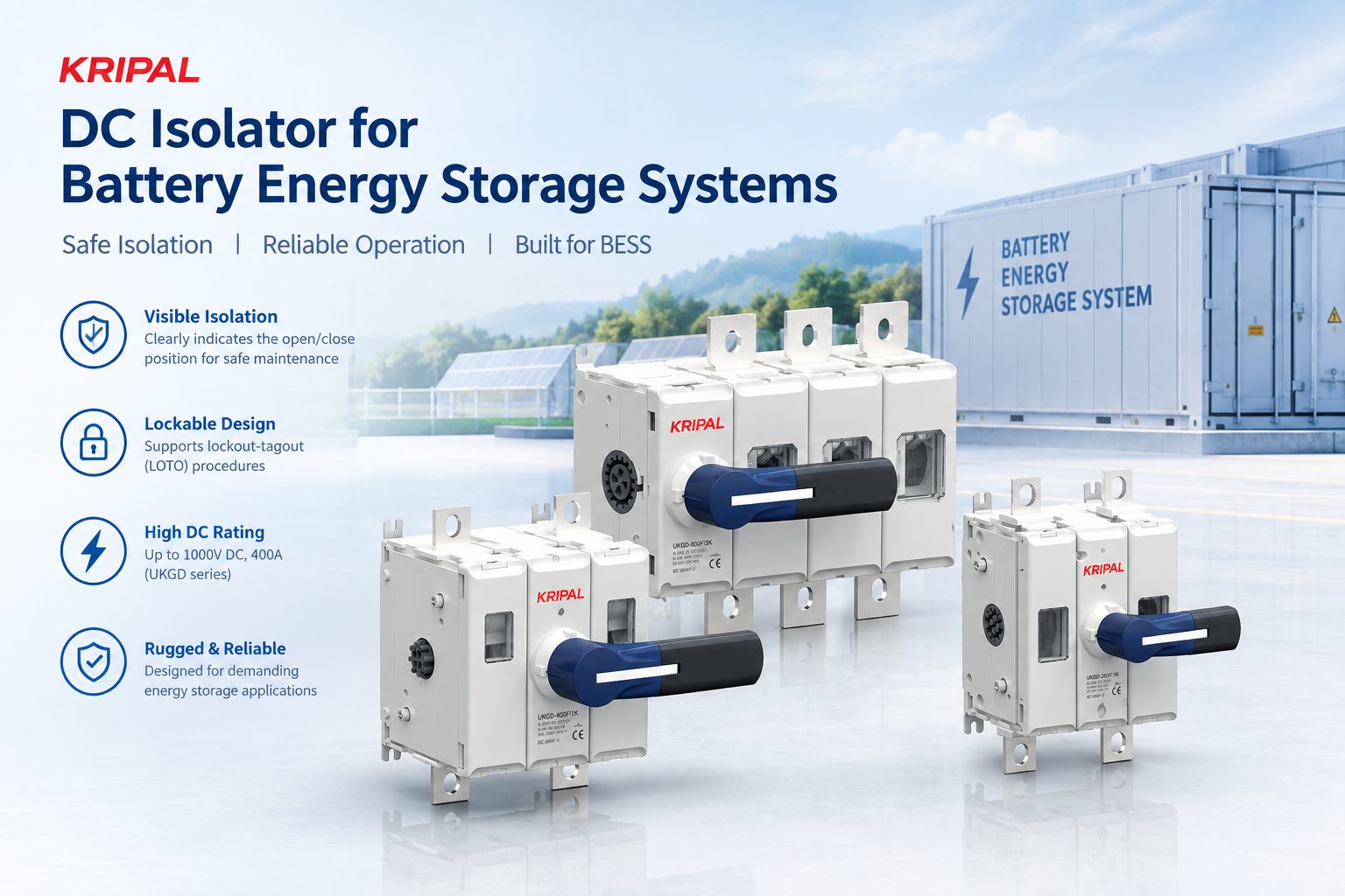
The isolator or disconnecting device serves a different purpose from the MCCB. It provides a reliable and verifiable means of separating the circuit for maintenance. Where required by the installation and safety procedure, the device should be lockable so the isolation status can be controlled during servicing.
- Voltage rating must cover the maximum system DC voltage.
- Continuous current rating must be suitable for the actual operating current and installation conditions.
- The device must be appropriate for DC switching/isolation at the specified voltage and current.
- The number of poles and switching arrangement should follow the system design and manufacturer instructions.
Lockability and Position Indication
Lockability and position indication should support the site’s maintenance and lockout/tagout procedure where applicable.
Selecting a BESS DC Fuse
A DC fuse can provide supplementary, backup, or current-limiting protection. Its selection involves more than choosing an ampere rating.
- Ampere rating: Select according to the continuous operating current, conductor protection requirements, and applicable design rules.
- DC voltage rating: The fuse must be rated for the maximum DC voltage of the circuit.
- Interrupting rating: The fuse’s interrupting rating must be sufficient for the maximum prospective fault current at its installation point.
- Clearing characteristics: Pre-arcing and total clearing behavior should be considered when coordinating the fuse with the MCCB and other protection.
- Coordination: Verify the fuse/breaker combination using manufacturer time-current curves and coordination data rather than assuming that one device will always clear before the other.
How to Size BESS DC Protection
Step 1: Determine the Maximum System Voltage
Do not size protection from nominal battery voltage alone. Determine the maximum operating and charging voltage from the battery manufacturer’s data and the system architecture. The selected MCCB, isolator, and fuse must have suitable DC voltage ratings for the actual circuit.
Step 2: Determine the Continuous Current
Start with the maximum continuous current of the battery/PCS circuit. Then consider conductor ampacity, ambient temperature, enclosure conditions, installation method, continuous-load requirements, and manufacturer derating. A fixed 25% rule should not be treated as a universal BESS sizing rule.
Step 3: Determine the Prospective Fault Current
The prospective fault current is a critical input to protection selection. Use the battery manufacturer’s short-circuit data and the system configuration, including parallel strings and relevant interconnection impedance, to establish the available fault current at the protection device location.
Step 4: Check the Interrupting Rating
The interrupting or breaking rating of each protection device must be suitable for the available fault current at its installation point. This is separate from the device’s continuous ampere rating. A device with an adequate continuous-current rating is not necessarily suitable for a high-fault-current application.
Step 5: Verify Protection Coordination
Where an MCCB and fuse are used together, verify coordination using manufacturer time-current curves, let-through/clearing characteristics where relevant, and published coordination tables. The objective is to ensure that the appropriate device clears the fault without compromising the protection of cables, busbars, battery strings, or connected equipment.
Example: What Information Is Needed Before Selecting a Device?
Consider a BESS DC circuit with a nominal voltage of 400 V and a continuous current of 100 A. These two values alone are not enough to select an MCCB, isolator, and fuse. The designer also needs the maximum operating/charging voltage, prospective fault current, conductor rating, environmental conditions, system topology, and the manufacturer’s device ratings.
- MCCB: DC voltage rating suitable for the maximum system voltage; continuous-current rating suitable for the actual load and installation; DC interrupting rating suitable for the prospective fault current.
- Isolator: DC voltage and continuous-current ratings suitable for the circuit, with an appropriate isolation function and lockable mechanism where required.
- Fuse: Suitable DC voltage, ampere, and interrupting ratings, with clearing characteristics that coordinate with the other protective devices.
BESS Battery String Protection
When multiple battery strings are connected in parallel, protection should be considered at the string level as well as at the bank level. The appropriate arrangement depends on the battery architecture and the contribution of each string to a fault. String-level fuses or breakers can help isolate a faulted string and limit fault contribution from the remaining strings, but the exact configuration should be verified against the battery manufacturer’s design and the applicable requirements.
Arc Flash and Installation Safety
BESS DC faults can create significant thermal and arc energy. Protection design therefore needs to consider more than the breaker or fuse rating. Enclosures, cable routing, mechanical protection, maintenance procedures, isolation practices, and the site’s risk assessment should all be considered as part of the overall protection strategy.
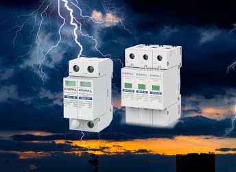
Projects may also require coordinated circuit protection devices and related surge protection devices depending on the system design and site requirements.
BESS DC Protection: MCCB vs Isolator vs Fuse
| Feature |
DC MCCB |
DC Isolator |
DC Fuse |
| Overload protection |
Yes, where provided by the trip unit |
No |
Application dependent |
| Short-circuit interruption |
Yes, within rated interrupting capability |
Not a protective function |
Yes, when appropriately rated |
| Reset after trip |
Normally yes |
Manual switching |
No; fuse replacement required after operation |
| Maintenance isolation |
May provide disconnection, but verify isolation requirements |
Primary function |
No |
| Key selection data |
Voltage, current, interrupting rating, trip characteristics |
Voltage, current, isolation/switching capability |
Voltage, ampere rating, interrupting rating, clearing characteristics |
Frequently Asked Questions
Can I use an AC MCCB on a DC battery circuit?
Do not assume that an AC-only MCCB is suitable for DC. Use a device only when the manufacturer provides an appropriate DC rating for the voltage, current, pole configuration, and application.
What voltage rating do I need for a 48 V battery system?
Do not select the device from the 48 V nominal value alone. Determine the battery’s maximum operating and charging voltage and select protection with a suitable DC voltage rating.
Do I need both an MCCB and a fuse on a BESS battery circuit?
Not necessarily in every design. The combination depends on the available fault current, MCCB interrupting capability, battery architecture, applicable requirements, and coordination. A fuse may be used as supplementary, backup, or current-limiting protection where appropriate.
What size isolator do I need for a 200 A battery circuit?
The isolator should be selected for the actual continuous operating current, maximum DC voltage, installation conditions, and the manufacturer’s rating. A universal 25% sizing rule should not be assumed.
How do I protect multiple parallel battery strings?
Consider string-level protection as well as bank-level protection. The exact fuse or breaker arrangement should be based on each string’s current, fault contribution, battery architecture, and coordination with the bank-level protection.
Can I use the same DC MCCB for solar and battery circuits?
Only if the device has the appropriate DC ratings and application suitability for both circuits. Solar and battery circuits can have different voltage, current, fault, and operating characteristics, so each circuit should be evaluated from its own data.
How KRIPAL Can Help With BESS DC Protection Selection
KRIPAL’s UKM5DC DC MCCB range is specified in the source material for DC applications up to 1500 V and 630 A, while the UKGD isolator range is specified for battery-side isolation up to 1000 V DC and 630 A. Final selection should always be verified against the actual system voltage, current, fault current, installation conditions, and the applicable requirements.
For a protection review, provide the battery nominal voltage, maximum charging voltage, maximum continuous current, available short-circuit current, number of parallel strings, and PCS/inverter rating. These data allow the protection arrangement to be evaluated before a specific device is selected. For control-side equipment, KRIPAL also offers contactors for suitable AC applications.
Conclusion
Reliable DC protection is a critical part of battery energy storage system design. DC MCCBs, isolators, and fuses each serve different protection or isolation functions, and their selection should be based on the system’s maximum voltage, continuous current, prospective fault current, interrupting capacity, and protection coordination requirements.
Rather than relying on nominal battery voltage or fixed sizing rules, engineers should evaluate the complete electrical system and verify device ratings against actual operating conditions and manufacturer specifications. Proper coordination between the battery, protection devices, conductors, and PCS/inverter helps improve system safety and reliable operation.
For BESS applications, KRIPAL provides DC protection solutions including the UKM5DC DC MCCB and UKGD DC isolator. If you are selecting protection devices for a battery energy storage project, contact our technical team with your system voltage, maximum continuous current, fault-current data, and battery configuration for application-specific guidance.
Request a Quote
Technical Disclaimer
This article is a general technical guide, not a substitute for a project-specific electrical design. Final protection selection should be verified using the battery and PCS manufacturer’s data, the calculated prospective fault current, conductor ratings, environmental conditions, device manufacturer instructions, and the applicable codes, standards, and site requirements.



 Search
 July 25, 2026