


 Search
Knowledge Center
How to Wire a Contactor: Step by Step Installation Guide
Learn how to wire a contactor for single-phase and three-phase motors, identify A1/A2 coil terminals, and build a safe DOL starter control circuit.
 June 18, 2026
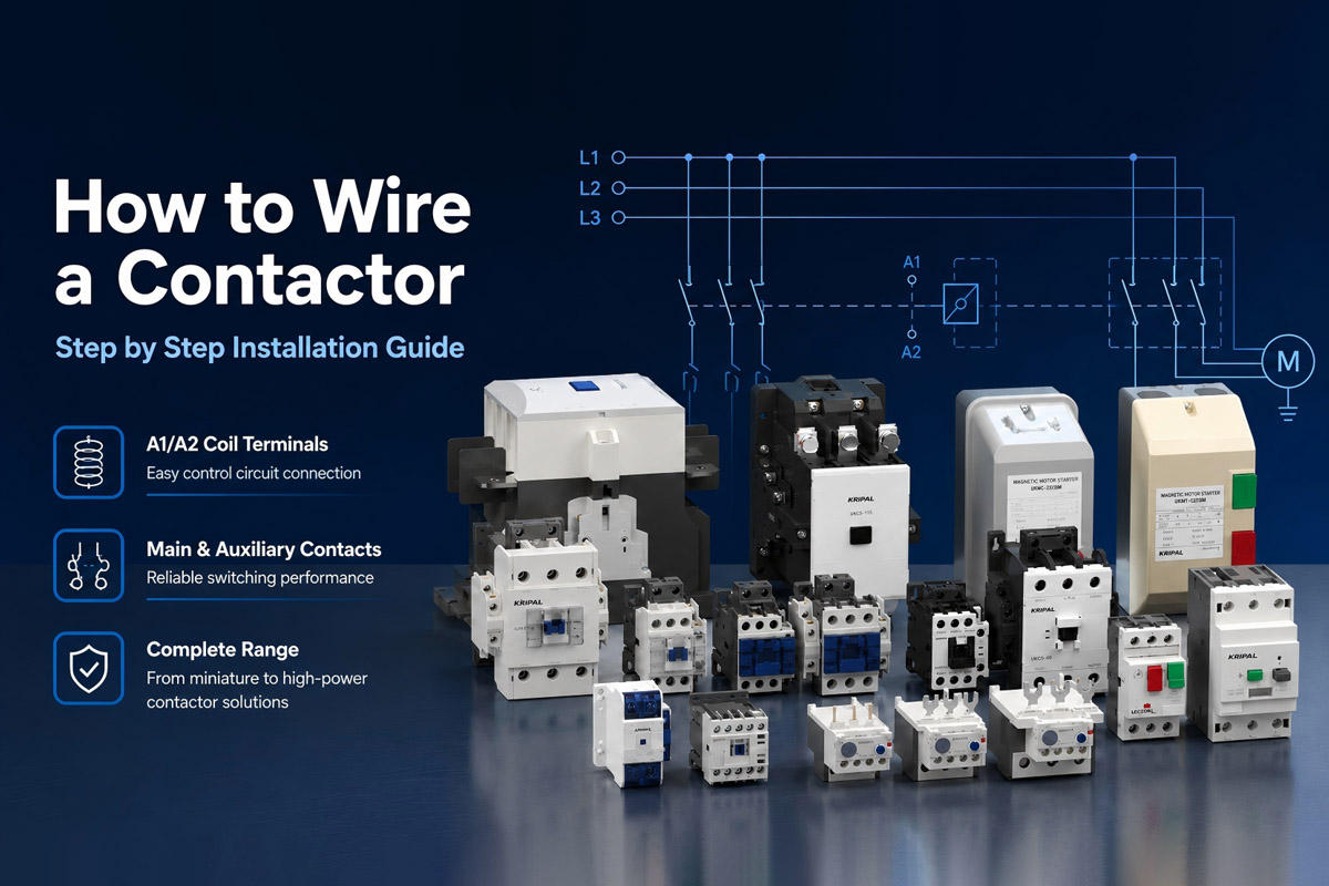
A contactor that is wired incorrectly can weld its contacts shut within the first few switching cycles. A short across the coil terminals can take out the control transformer. This guide walks through single-phase and three-phase contactor wiring, coil terminal identification, main and auxiliary contact usage, and the DOL motor starter circuit.
Understanding Contactor Terminal Markings
A1 and A2 Coil Terminals
Every IEC contactor has two coil terminals marked A1 and A2. These terminals energize the electromagnet that pulls the main contacts closed. The physical location of A1 and A2 terminals depends on the contactor design. Always verify the terminal markings on the product label before wiring. Some models provide a second A2 terminal on the opposite side to simplify wiring in tight panels.
The coil voltage must match the control circuit. Common coil voltages include 24V DC, 110V AC, 230V AC, and 400V AC. The voltage rating is printed on the contactor side label. A 24V DC coil connected to 230V AC will burn out immediately. Always verify the coil voltage before connecting.
Main and Auxiliary Contacts
Main contacts carry the load current to the motor or heater. They are numbered 1/L1, 3/L2, 5/L3 on the line side and 2/T1, 4/T2, 6/T3 on the load side. These contacts are rated for the full load current and are normally open in standard contactors.
Auxiliary contacts handle control signals only. They switch small currents for control circuits, indicator lamps, and PLC inputs. Auxiliary contacts are numbered with two digits. The first digit indicates position, the second indicates function. For normally open auxiliary contacts, the numbers are 13-14 for the first contact and 23-24 for the second. For normally closed auxiliary contacts, the numbers are 11-12 and 21-22.
Single-Phase Contactor Wiring
Single-phase contactor wiring connects one pole of the contactor in series with the line conductor. Follow this procedure:
- Mount the contactor on a DIN rail inside the enclosure
- Connect the line supply to terminal 1/L1
- Connect the load to terminal 2/T1
- Connect the neutral supply to terminal 3/L2
- Connect the load neutral to terminal 4/T2
- Wire the control circuit to A1 and A2 through a control switch or relay
For a single-pole switching application, only one pole carries the load current. The unused pole may remain unused or can be used according to the manufacturer’s wiring instructions. A control fuse rated at 2A to 6A protects the coil circuit against short circuits.
Standard Three-Phase Motor Control
A three-phase contactor uses all three main poles. The wiring follows the same terminal numbering. L1 to T1, L2 to T2, and L3 to T3. A three-pole motor protection circuit breaker or manual motor starter sits between the main supply and the contactor.
Three Phase Motor Contactor Wiring Sequence
- Supply connections. L1 to contactor terminal 1/L1, L2 to 3/L2, L3 to 5/L3
- Motor connections. Contactor terminal 2/T1 to motor U, 4/T2 to motor V, 6/T3 to motor W
- Coil wiring. A1 to control supply line, A2 to control circuit return through start/stop pushbuttons and overload relay NC contact
- Overload relay. Mount directly below the contactor, with motor leads passing through the thermal elements
For the UKC2 and UKC5 series, Kripal provides matching thermal overload relays that clip directly onto the contactor output terminals. This eliminates the need for separate wiring between the contactor and overload relay body.
DOL Starter Wiring
A Direct-On-Line starter is the simplest motor starting method. The contactor closes directly onto the full line voltage. The control circuit includes a start pushbutton with a normally open contact, a stop pushbutton with a normally closed contact, and the overload relay NC contact wired in series with the contactor coil.
The holding contact, or seal-in contact, is a normally open auxiliary contact wired in parallel with the start pushbutton. When the contactor energizes, the auxiliary contact closes and maintains the coil circuit after the start button is released. Pressing the stop button or tripping the overload relay breaks the holding circuit and the contactor drops out.
Comparing Single Phase and Three Phase Wiring
| Feature | Single Phase Wiring | Three Phase Wiring |
|---|---|---|
| Number of load poles used | 1 or 2 | 3 |
| Typical load current | Up to 32A | Up to 800A |
| Coil voltage common values | 230V AC, 24V DC | 24V DC, 110V AC, 230V AC, 400V AC |
| Overload protection | Single phase thermal overload | Three phase thermal or electronic overload relay |
| Typical application | Lighting, heating, small pumps | Motors, compressors, conveyors |
| Recommended series | UKC1, UKC2 up to 40A | UKC2, UKC5 for higher ratings |
Control Circuit Wiring
Run control wiring separately from power wiring
Use different cable trays or maintain at least 100mm separation inside the panel. Power cables carrying motor starting currents induce noise in control circuits that can cause contactor chatter or false triggering of PLC inputs.
Color coding simplifies troubleshooting
Follow the wiring color requirements specified by local electrical standards. Color conventions vary between regions. Label every wire at both ends with numbered ferrules matching the schematic. A panel with unlabeled wiring doubles troubleshooting time during commissioning and maintenance.
Protect the coil circuit with a control fuse
A 2A glass fuse on the secondary side of the control transformer prevents a shorted coil from damaging the transformer. For DC control circuits, use DC-rated fuses or miniature circuit breakers.
Installation Safety
- Verify main power is isolated before connecting any wiring. Lock out and tag out the upstream circuit breaker. Use a contact voltage tester on all terminals. Never assume a circuit is dead because a breaker handle is in the off position.
- Tighten terminal screws to the torque specified on the contactor. A loose connection generates heat at the terminal. Over time this heat degrades the conductor insulation and can cause a terminal block fire. A torque screwdriver set to the manufacturer specifications prevents both loose connections and stripped threads.
- After wiring is complete, test the control circuit before applying main power. Energize the coil without main power present and verify the contactor pulls in with a positive click. Check that the auxiliary contacts change state. Then apply main power and measure the voltage at the load terminals.
Next Steps
Browse Kripal capacitor switching contactors from the UKC1 series, rated 50A to 85A for capacitor banks up to 50kVAR. For technical selection support, contact Kripal engineering with your PFC panel specifications.
Explore our full range of AC contactors for motor and industrial control applications.
Frequently Asked Questions
Q: What happens if I reverse A1 and A2 on the coil terminals?
For AC coils, polarity does not matter. A1 and A2 can be connected either way and the coil will energize correctly. For DC coils on contactors with built-in surge suppression, polarity matters. The suppression diode or varistor is wired in a specific direction. Reverse polarity on a DC coil with suppression can short the control circuit. Check the contactor side label. If the A1 terminal is marked with a plus sign, connect the positive DC lead to A1.
Q: Can I use a three-phase contactor for a single-phase load?
Yes. Use any two poles for the single-phase circuit. The third pole can be unused or wired as an additional contact in series for extra breaking capacity. The contactor thermal current rating does not change, but the AC-1 utilization category rating applies when switching resistive single-phase loads like heaters.
Q: What is the difference between a contactor and a relay?
A contactor is designed for switching high-power loads such as motors, heaters, and industrial equipment, while a relay is mainly used for low-power control and signal switching. Contactors typically have higher current ratings and stronger arc suppression for frequent load switching.
Q: Can a contactor switch DC loads?
Yes, but only if the contactor is specifically rated for DC applications. DC switching requires suitable contact design and arc suppression. Always check the contactor’s DC voltage and current ratings before use.
Q: Why does my contactor chatter instead of closing cleanly?
Contactor chatter has three common causes. The control voltage may be below the coil pull-in threshold, typically 85 percent of rated coil voltage. Dirt or debris on the magnet faces prevents the armature from seating flat. Excessive voltage drop on the control circuit under inrush can also starve the coil long enough to cause oscillation. Check the control supply with the contactor connected and measure the voltage at A1 and A2 during the closing attempt.
Q: Do I need a surge suppressor across the contactor coil?
When the contactor coil is switched by a PLC output or a sensitive electronic relay, a surge suppressor across the coil terminals protects the switching device from voltage spikes. The collapsing magnetic field in the coil generates a high-voltage transient at turn-off. A varistor or RC suppressor circuit wired in parallel with A1 and A2 absorbs this energy. Kripal contactors can be ordered with built-in coil suppression as a factory option for the UKC1 and UKC2 series.
Related Resources
Explore Knowledge Center >
Need a matching KRIPAL product?
Share voltage, quantity and destination. An engineer will reply with options and lead time.
