



Knowledge Center
How to Manage Electrical Spare Parts and Check Contactor Interchangeability
Essential guide to managing electrical spare parts and evaluating contactor interchangeability: master AC-3 ratings, coil matching, and mechanical equivalence.
 August 23, 2026
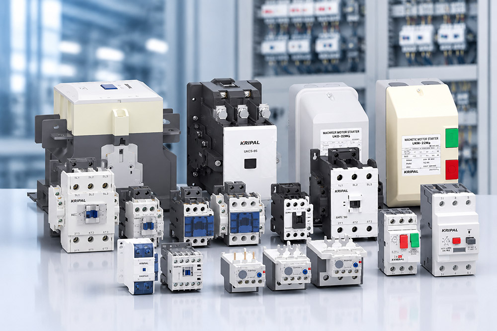
A spare parts list is often created when an electrical installation is commissioned but used years later, when the original installer or maintenance engineer may no longer be available. When a component fails, the person responsible for the repair must decide whether an alternative device can safely replace the original one. The quality of the spare parts list determines whether that decision is straightforward or becomes a costly maintenance problem.
For industrial control panels, motor control systems and electrical distribution equipment, spare parts management involves more than keeping replacement components in stock. It requires understanding which devices are electrically and mechanically compatible, which accessories can be shared across a product range, and where substitution introduces additional risks.
This guide explains how to evaluate electrical spare parts, check contactor interchangeability and build a practical spare parts list. The approach is based on published product ratings, manufacturer compatibility information and the actual operating requirements of the installation.
Why Interchangeability Counts
A device failure during production can cost considerably more than the replacement component itself. The real cost is often determined by how long the equipment remains out of service. A replacement that can be installed immediately may restore production quickly, while an incompatible substitute can require additional wiring, mechanical modifications or further engineering checks.
The spare parts strategy established during commissioning therefore has a direct effect on future maintenance costs and equipment availability.
Downtime
A direct replacement generally requires only the time needed to isolate the equipment, remove the failed component, install the replacement and complete the necessary electrical checks.
A substitute that is electrically suitable but mechanically different may take longer to install because mounting arrangements, terminal positions or wiring connections need to be adapted. An unsuitable substitute that appears to fit can be even more problematic, as its incompatibility may only become apparent during operation.
For this reason, replacement decisions should be based on verified electrical and mechanical compatibility rather than physical appearance or nominal current rating alone.
Stock Holding
A spare parts list organized around compatible product groups can reduce the number of individual components that need to be held in stock.
For example, several machines may use contactors from the same product family, and some auxiliary contact blocks may be compatible across multiple frame sizes. Where the manufacturer confirms this compatibility, a common spare can support more than one installation.
However, components should not be treated as interchangeable simply because they belong to the same product range. Coil specifications, contact configurations, mounting arrangements and accessory compatibility must be checked against the manufacturer’s documentation.
The objective is to reduce unnecessary inventory without introducing additional maintenance or safety risks.
What Makes Two Devices Interchangeable
Interchangeability is determined by a combination of published electrical ratings, mechanical dimensions and application-specific requirements. Two devices may look similar and carry the same nominal current rating but still differ in important operating characteristics.
A single incompatibility can make a proposed replacement unsuitable.
Electrical Equivalence
The rated operational current (Ie) under the relevant utilization category is one of the first parameters to compare. Thermal current (Ith) alone is not sufficient to establish that two contactors are electrically equivalent.
The rated operational voltage (Ue), utilization category and intended switching duty must also be considered. For example, AC-1, AC-3 and AC-4 describe different operating conditions. A contactor selected for resistive loads under AC-1 conditions should not automatically be considered suitable for motor switching under AC-3 or AC-4 conditions.
The control coil must match the control supply in both voltage and current type. An AC coil and a DC coil are not interchangeable simply because their nominal voltage figures are the same. For AC coils, the rated frequency must also be compatible. Where relevant, the coil’s operating voltage range and any required suppression accessories should be checked.
Auxiliary contacts are another important part of electrical equivalence. The number and arrangement of normally open (NO) and normally closed (NC) contacts must satisfy the control circuit requirements. Their electrical ratings and utilization category should also be appropriate for the connected circuit.
Where auxiliary contacts are used in safety-related control functions, the replacement must be assessed against the requirements of the complete safety-related control system. A standard auxiliary contact should not be assumed to provide a safety function without the necessary manufacturer specifications and system-level verification.
For motor protection, the overload relay must have an adjustment range that covers the motor’s rated current. Its trip class, protection characteristics, mechanical compatibility with the contactor and coordination with the upstream short-circuit protective device must also be verified.
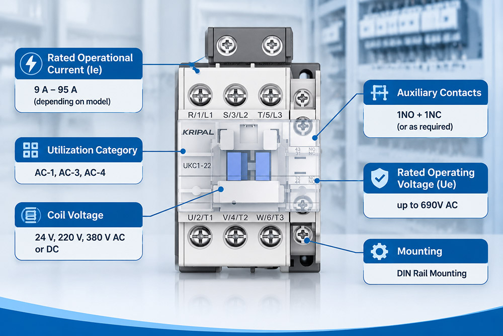
Mechanical Equivalence
Mechanical compatibility involves more than whether a replacement device fits onto the existing mounting rail.
The overall width, height and depth, mounting method, fixing-hole positions, terminal orientation and conductor capacity all need to be checked. Required installation clearances and ventilation conditions should also be considered.
Accessories are equally important. Auxiliary contact blocks, overload relays, mechanical interlocks and other attachments may have specific compatibility requirements within a manufacturer’s product range.
A replacement that fits the available mounting space may still require changes to the control wiring or accessory configuration. These differences should be identified before the replacement is purchased or installed.
The following checklist summarizes the main parameters that should be compared when evaluating a contactor replacement:
| Check Item | Why It Matters | Common Oversight |
|---|---|---|
| Rated operational current (Ie) | Confirms suitability under the intended utilization category | Comparing thermal current (Ith) instead |
| Utilization category and Ue | Establishes the applicable switching duty and voltage rating | Assuming the same current rating means the same duty |
| Coil voltage and type | Ensures compatibility with the control supply | Confusing AC and DC coils |
| Auxiliary contact configuration | Maintains the required NO/NC control functions | Checking contact quantity but not arrangement |
| Overload relay setting range | Ensures suitability for the protected motor | Matching the relay to the contactor frame rather than motor current |
| Mounting and dimensions | Confirms physical installation compatibility | Checking width but overlooking depth and fixing positions |
| Accessories and terminals | Ensures correct connections and attachment compatibility | Assuming accessories are shared across all frames |
Where Substitution Is Not Safe
A replacement device that appears to satisfy the main published ratings may still be unsuitable if its application qualifications or installation conditions differ from those of the original component.
The following situations require particular attention before any substitution is approved.
Duty Category
A contactor rated for resistive switching under AC-1 conditions is not automatically suitable for motor switching under AC-3 conditions, even when both devices have the same rated operational current.
The utilization category describes the operating conditions for which the contactor has been rated. It is therefore an essential part of the selection process rather than simply a descriptive label.
AC-3 is commonly associated with starting squirrel-cage motors and switching them off while running. AC-4 covers more demanding operations, including inching, plugging and reversing. These operations can impose significantly greater electrical stress on the contactor.
When replacing a contactor in an application involving frequent starting, reversing or inching, the relevant AC-4 ratings and electrical endurance must be checked rather than relying on an AC-3 rating alone.
Application-Specific Qualification
A device’s suitability depends on its declared ratings and qualifications under the intended operating conditions. A rating established for one utilization category should not be assumed to apply to another.
The same principle applies to installation conditions, operating frequency and environmental requirements. A replacement should be assessed against the actual application, not simply the original device’s frame size or appearance.
Common substitution mistakes include:
A successful replacement should restore the original function without introducing new electrical, mechanical or operational limitations.
Building a Spares List
A useful electrical spare parts list should record not only which components are held in stock but also why they are required and which equipment they support.
Part numbers alone may become difficult to interpret when personnel change, equipment is modified or the original installation documentation is no longer available. Recording the application and compatibility requirements makes the list more useful throughout the equipment’s service life.
What to Record
Each entry should identify the device type, manufacturer, model number and product frame. For contactors, the coil voltage, AC or DC coil type, rated operational current, utilization category and auxiliary contact arrangement should also be recorded.
Where applicable, include the overload relay model, accessory references, mounting dimensions and the machines or control panels supported by the spare.
It is also useful to record whether a component is a direct replacement or an approved alternative. Any restrictions on its use should be clearly documented.
For example, an alternative contactor may be electrically suitable for a particular motor application but require a different auxiliary block or mounting arrangement. Recording this information prevents maintenance personnel from assuming that the device is a universal replacement.
A practical contactor replacement record should include the following:
| Information | Example or Description |
|---|---|
| Original contactor model | Manufacturer and complete model reference |
| Replacement model | Verified alternative model |
| Rated operational current | According to the intended utilization category |
| Utilization category | AC-1, AC-3 or AC-4, as applicable |
| Coil specification | Voltage, AC/DC type and frequency where applicable |
| Auxiliary contacts | NO/NC configuration and electrical ratings |
| Overload relay | Model, setting range and trip class |
| Mechanical details | Dimensions, mounting and terminal arrangement |
| Supported equipment | Machine, panel or installation reference |
| Compatibility status | Direct replacement or approved alternative |
How Many to Hold
The appropriate spare parts quantity depends on equipment criticality, failure history, supplier lead time and the financial impact of downtime.
A component used in a production line that cannot operate without it may justify holding multiple spare units. A component used in equipment with an available bypass or alternative production route may require a different inventory strategy.
The decision should also account for whether the manufacturer maintains local stock, how quickly replacement products can be delivered and whether the component is likely to become obsolete.
Rather than applying a fixed quantity to every device, spare parts levels should be reviewed whenever equipment configurations, production requirements or operating conditions change.
Holding a Spare or Adapting One
The decision between stocking a complete replacement and adapting an available component should be made before a failure occurs. It depends primarily on the consequences of equipment downtime and the technical feasibility of the proposed replacement.
A machine that can stop an entire production line may justify holding a complete spare contactor assembly, including the correct frame, coil and required contact blocks. For equipment that affects only one operation among several, holding the most frequently used compatible frames and accessories may be sufficient. Where equipment can operate safely through an approved bypass or alternative process, ordering a replacement after failure may be a reasonable option, provided the associated delivery time and downtime risk are acceptable.
The middle situation requires particular attention. Adapting a device in a hurry can result in an unverified substitution, especially when the coil, auxiliary contacts or mounting accessories are assumed to be compatible. Where the manufacturer provides replaceable coils, keeping compatible spare coils for commonly used frames can reduce recovery time. However, compatibility must be confirmed by exact model, frame size and control voltage. Auxiliary blocks and overload relays should be treated in the same way.
A shared spare is useful only when its compatibility has been established and documented.
For further technical guidance, see our related guide on reading contactor specifications and circuit diagrams, as well as our guide to normally open and normally closed auxiliary contacts. These resources help maintenance personnel identify the electrical requirements before selecting a replacement.
Frequently Asked Questions (FAQs)
Can two contactors with the same rated current be used interchangeably?
Not necessarily. The rated operational current alone does not establish interchangeability. The utilization category, rated operational voltage, coil specifications, auxiliary contact configuration, mechanical dimensions and accessory compatibility must also be checked against the original application.
Can I replace an AC contactor with another brand’s contactor?
Yes, provided the replacement meets the electrical and mechanical requirements of the application. Check the rated current under the relevant utilization category, coil voltage and type, terminal arrangement, mounting dimensions and auxiliary contact configuration. Manufacturer documentation should be used to confirm compatibility before installation.
Are contactor coils interchangeable within the same product series?
Not always. Coil compatibility depends on the exact contactor model, frame size, rated control voltage and AC or DC supply type. For AC coils, frequency compatibility must also be verified. Always consult the manufacturer’s product catalog or compatibility documentation before replacing a coil.
Can auxiliary contact blocks be shared between different contactor models?
Only when the manufacturer confirms compatibility. Auxiliary contact blocks may differ in mounting position, physical dimensions, contact arrangement and electrical ratings. Even contactors within the same product family may require different auxiliary contact blocks.
How many spare contactors should an industrial facility keep in stock?
There is no universal quantity. The required stock depends on equipment criticality, failure history, supplier lead time, replacement availability and the cost of production downtime. Critical equipment with long replacement lead times may justify keeping additional complete contactors, while less critical applications may require fewer spares.
What information is needed to identify a compatible replacement contactor?
The most useful information includes the original manufacturer’s name and model number, a clear nameplate photograph, rated operational current, utilization category, coil voltage and AC/DC type, auxiliary contact arrangement, overload relay configuration and mounting dimensions. Providing these details helps the supplier evaluate a suitable replacement more accurately.
Final Notes
Effective spare parts management is not simply about keeping more electrical components in stock. It is about knowing which components can be replaced, which accessories can be shared and which differences require further engineering verification. For industrial contactor applications, checking the rated operational current, utilization category, coil specifications, auxiliary contact arrangement, overload protection and mechanical dimensions helps reduce the risk of unsuitable substitutions.
KRIPAL offers AC contactor solutions across different product ranges and current ratings. For example, the relevant three-pole contactor range includes models with rated current options from 9 A to 95 A, with coil options available in specified configurations. Exact ratings, coil specifications and accessory compatibility should always be confirmed against the catalogue for the selected model.
If you are reviewing your existing contactor stock or looking for compatible replacement devices, KRIPAL can help assess the requirements based on the original model, nameplate information and control circuit configuration.
To support a more accurate selection, please provide:
Contact the KRIPAL team to discuss contactor replacement and spare parts requirements.
Related Resources
Explore Knowledge Center >

Need a matching KRIPAL product?
Share voltage, quantity and destination. An engineer will reply with options and lead time.
