



Knowledge Center
DC Earthing Arrangements: PV, Battery and IT Systems
Explore DC earthing arrangements in solar PV and battery systems: unearthed IT vs midpoint grounding, insulation monitoring devices, and DC protection equipment.
 August 20, 2026
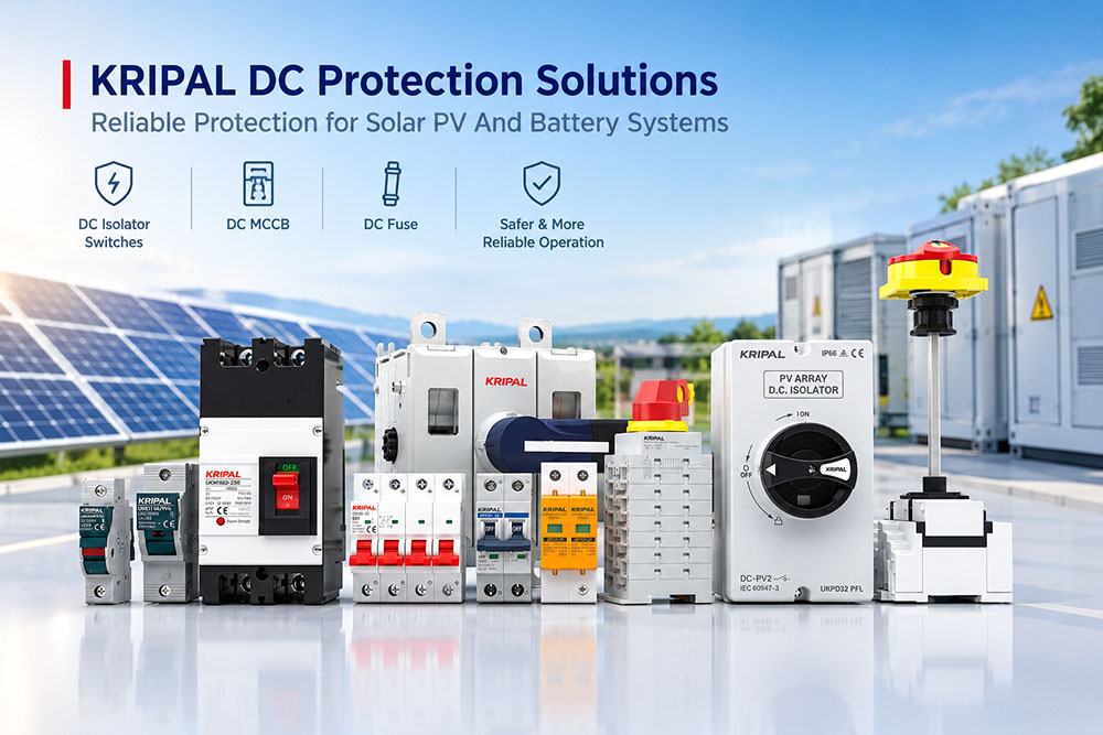
Direct-current (DC) installations can use different earthing arrangements, and the arrangement selected affects insulation monitoring, fault-current paths, and the choice of protective devices. An unearthed PV circuit behaves differently from a circuit with one pole intentionally earthed. A battery string with a midpoint earth introduces another set of design considerations.
This guide explains the main principles relevant to solar PV and battery systems. The exact requirements depend on the inverter or converter topology, installation rules, equipment manufacturer instructions, and the system’s rated voltage. The examples below are design guidance, not a substitute for a project-specific protection study.
What Earthing Does on a DC System
Protective Earthing
Protective earthing connects exposed conductive parts, such as metal enclosures, to the installation’s protective earthing system. Its purpose is to reduce electric-shock risk and help protective measures operate as intended if insulation fails. The fault-current path and the means of automatic disconnection depend on the source, earthing arrangement, and protective-device design.
A protective-earth connection must be correctly sized, installed, and verified in accordance with applicable rules. Continuity testing is an important part of inspection and commissioning, but it is not the only element of a complete verification process. A metal enclosure should never be assumed to be protectively earthed merely because it is mounted on a metal structure.
Functional Earthing
Functional earthing is a connection to earth made for the correct operation or performance of equipment, rather than solely for protection against electric shock. Depending on the design, a functional connection may define a circuit reference or support electromagnetic compatibility and monitoring. It must not be confused with protective earthing, although a design may combine functions where applicable requirements permit it.
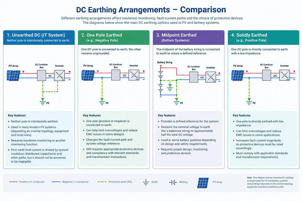
In an unearthed DC circuit, neither live pole is intentionally connected to earth. The pole-to-earth voltages are influenced by insulation resistance, distributed capacitance, filters, connected equipment, and any existing insulation fault. “Unearthed” therefore does not mean that conductors are always at zero volts to earth or that they are safe to touch.
Why Some Photovoltaic Arrays Use Unearthed DC Circuits
Many modern PV systems use unearthed DC circuits, but this is not universal. The permitted arrangement depends on inverter topology, PV equipment, local installation requirements, and manufacturer instructions. The DC circuit arrangement must be assessed separately from the protective earthing of module frames, mounting structures, and equipment enclosures.
The IT Arrangement and the First Earth Fault
In an IT system, live conductors are isolated from earth or connected to earth through a sufficiently high impedance, as defined by the relevant system design. When the first insulation fault connects a live conductor to earth, the resulting current is influenced by the system’s insulation impedance, distributed capacitance, and other paths to earth. It may be limited, but it should not automatically be assumed to be negligible.
Depending on the design and applicable rules, an IT system may continue operating after a first insulation fault while the fault is detected and located. A second fault involving another live conductor can create a much more severe fault path. The first fault should therefore be investigated promptly; whether continued operation is permitted is a decision for the responsible designer or operator under relevant safety requirements.
An unearthed arrangement does not, by itself, eliminate electric-shock risk. The voltage between a conductor and earth can change substantially when an insulation fault occurs, and a person’s exposure depends on the complete circuit and contact conditions. Safe isolation, suitable equipment, and required protective measures remain essential.
Design Implications
Unearthed DC systems require insulation monitoring or another monitoring function where specified by system design and applicable standards. Protective devices must also be suitable for the circuit’s maximum operational voltage, polarity, and possible current paths. Do not assume that a device suitable for a grounded circuit is automatically suitable for an unearthed PV circuit.
For a PV circuit with a maximum system voltage of 1,500 V DC, insulation coordination must consider the maximum voltage to earth that can occur in normal operation and under relevant fault conditions. Cable insulation, switchgear ratings, and inverter requirements should be selected from actual system design and equipment documentation, not from an assumption that each pole will normally remain at half the system voltage to earth.
Battery Systems and Mid-Point Earthing
Why a Mid-Point Earth May Be Used
Some DC systems use a midpoint connection to earth to establish a defined reference and, in a suitably balanced circuit, reduce nominal voltage from each pole to earth to approximately half the total DC voltage. Whether this arrangement is appropriate for a battery system depends on battery architecture, converter topology, grounding policy, and applicable requirements. It should not be adopted solely to reduce insulation ratings without a full system review.
The midpoint conductor and its connections must be designed for electrical stresses that can occur under normal and fault conditions. Its required cross-section, routing, and protection depend on the actual circuit and applicable rules. A small monitoring wire must not be treated as a protective or fault-current conductor unless it is specifically designed and approved for that duty.
What Changes When a Fault Occurs
A pole-to-earth fault in a midpoint-earthed system can create a fault-current path whose magnitude depends on source impedance, fault location and resistance, grounding connection, and the rest of the circuit. The midpoint connection does not, on its own, establish fault current or guarantee that an overcurrent device will operate.
Protection coordination must therefore be based on a project-specific fault analysis. Check prospective fault current, DC voltage and polarity, protective device DC breaking capacity, and permitted wiring arrangements. Voltage measurements can help with diagnosis, but they should be interpreted alongside circuit diagrams and protection studies.
Comparing Common DC Earthing Arrangements
| Arrangement | Pole-to-Earth Voltage | Possible First-Fault Response | Typical Monitoring / Protection |
|---|---|---|---|
| Unearthed / IT | Not fixed; can shift with insulation, capacitance, and faults | Fault current may be limited, but is not necessarily negligible | Insulation monitoring where required; fault-location process; coordinated protection |
| One pole solidly earthed | One pole is referenced to earth; the other is near full system voltage | A fault from the unearthed pole to earth may create a high-current path | Protection designed for the actual fault loop and grounding scheme |
| Mid-point earthed | Approximately half system voltage per pole only under suitable balanced conditions | Fault current depends on circuit topology and fault path | Project-specific overcurrent protection and voltage/insulation checks |
| Resistively earthed | Depends on grounding impedance and system conditions | Current may be limited by grounding impedance | Monitoring and protective response specified by design |
These are conceptual comparisons, not universal performance guarantees. Actual voltage and fault-current values must be established from system design, equipment instructions, and applicable installation rules.
Detecting an Earth Fault in an Unearthed System
Insulation Monitoring
An insulation monitoring device (IMD) monitors insulation resistance between an unearthed IT system and earth. Its measurement method depends on device design; it is not accurate to describe every IMD as simply applying a small voltage and measuring resulting current. IEC 61557-8 specifies requirements for IMDs used with unearthed IT systems, including DC IT systems up to 1,500 V DC within its stated scope.
The alarm threshold must be selected in accordance with applicable requirements, equipment manufacturer instructions, and installation normal characteristics. Distributed cable capacitance, filters, and connected power-electronic equipment can affect monitoring behavior. A default setting should not automatically be assumed either correct or incorrect: it must be checked against the actual installation.
Responding to an Insulation Alarm
An insulation alarm should be handled under a defined operating and maintenance procedure. Do not simply reset an alarm without investigating the cause. Depending on installation risk assessment and operating rules, the response may involve controlled isolation, fault location, and repair before the system is returned to service.
Fault-location equipment may help identify the affected circuit, but the method depends on system design and installed monitoring equipment. Record the alarm, operating state, and measurements, and follow manufacturer instructions for safe testing and isolation.
Common Design and Installation Errors
- Earthing one pole of a PV circuit without reassessing inverter requirements, protective devices, and complete system design.
- Assuming that an unearthed circuit has no hazardous voltage to earth or that its first earth fault is always negligible.
- Using a monitoring conductor as a midpoint or protective conductor without verifying that it is designed for required electrical duty.
- Setting an insulation-monitoring threshold without checking device instructions and installation normal characteristics.
- Treating an insulation alarm as a nuisance and resetting it without investigating the cause.
- Assuming that a metal enclosure or mounting structure automatically provides verified protective-earth continuity.
- Changing earthing arrangements after commissioning without reviewing insulation coordination, protection settings, device ratings, and wiring.
Commissioning Checks for an Unearthed DC System
Commissioning should be carried out by qualified personnel using procedures appropriate to equipment and installations. The checks below are a planning guide; the actual sequence, test method, and acceptance criteria must follow applicable standards and manufacturer instructions.
- Confirm intended earthing arrangements against approved drawings and inverter/converter documentation.
- Verify protective-earth continuity for exposed conductive parts using the prescribed test method.
- Check that the insulation-monitoring function is suitable for the system and configured in accordance with manufacturer instructions.
- Record relevant insulation-resistance readings only using a test procedure compatible with connected equipment; isolate or disconnect sensitive equipment where required.
- Measure pole-to-earth voltages where appropriate and interpret results against expected system configuration and operating states.
- Confirm that DC switches, circuit breakers, and fuses have suitable voltage ratings, polarity requirements, utilization categories, and breaking/withstand ratings for their intended duty.
- For a midpoint-earthed system, verify grounding connections and conductor design against approved drawings and fault studies.
- Record test conditions, results, instrument details, and alarms so that future maintenance can compare like-for-like measurements.
Selecting DC Switching and Protection Equipment
The earthing arrangement is one input to equipment selection, but it does not replace normal rating checks. For a DC switch-disconnector, verify rated operational voltage, current, utilization category, pole count, polarity, and permitted connection diagrams. For a DC circuit breaker or DC fuse, verify applicable DC breaking capacity and coordination with prospective fault current. Correct selection depends on exact circuits and manufacturer data.
IEC 60947-3 covers switches, disconnectors, switch-disconnectors, and fuse-combination units within its stated voltage scope, including up to 1,500 V DC. DC-PV utilization categories address different PV switching conditions; DC-PV2 is associated with PV circuits where significant overcurrent may occur and current may flow in both directions, such as certain parallel-string arrangements. Do not treat DC-PV2 and DC-21B as interchangeable categories.
A product datasheet may state a short-time withstand current for a defined duration, such as 780 A for one second. That figure must be interpreted according to declared product characteristics and test conditions. It is not automatically the same as rated short-circuit breaking capacity, and it should not be used as evidence that the device can interrupt that current.
For projects using KRIPAL DC switch-disconnectors, DC circuit breakers, or fuses, confirm the exact model and published ratings against circuit design. Product suitability should be established from datasheets and wiring instructions rather than inferred from a general article.
Matching the Earthing Arrangement to Plant Operation
An earthing arrangement affects how the system responds to insulation faults and what monitoring or protective measures are needed. An unearthed IT system may be designed to remain in operation after a first insulation fault, but only where applicable requirements and operating procedures permit it and suitable monitoring and fault response are provided. Earthed systems create different fault-current paths and require protection designed for those conditions.
The decision is an engineering and operational choice, not simply a cost comparison. Consider continuity-of-service requirements, personnel safety, maintenance capability, inverter or battery topology, local rules, and ratings of all connected devices.
For a project-specific review, provide DC system voltage, earthing arrangements, prospective fault currents where known, circuit diagrams, and intended switching/protection functions. These details help determine which product ratings need verification. KRIPAL can review applicable product ranges against project requirements; final system design and compliance remain the responsibility of the project’s qualified designer. Get in touch with our team via our Contact Us page.
Frequently Asked Questions (FAQ)
What is a DC earthing arrangement?
A DC earthing arrangement defines how live DC conductors relate to earth and how exposed conductive parts are protectively earthed. It affects pole-to-earth voltages, fault-current paths, insulation monitoring, and the selection of protective devices. The suitable arrangement depends on system design, equipment instructions, and applicable installation rules.
Does an unearthed DC system mean that it is safe to touch?
No. Unearthed means that neither live pole is intentionally connected to earth; it does not mean that conductors are at zero volts to earth or safe to touch. Pole-to-earth voltage can change during an insulation fault, so suitable isolation, protective measures, and safe working procedures remain essential.
What happens when the first earth fault occurs in a DC IT system?
The first earth fault connects a live conductor to earth. The resulting current depends on the system’s insulation impedance, distributed capacitance, and other paths to earth, so it may be limited but should not automatically be considered negligible. Whether the system may continue operating must follow applicable requirements and the operator’s fault-response procedure.
Do all solar PV systems use an unearthed DC arrangement?
No. Many modern PV systems use unearthed DC circuits, but the permitted arrangement depends on inverter topology, PV equipment, manufacturer instructions, and local installation requirements. The earthing of the DC circuit should also be distinguished from protective earthing of module frames, mounting structures, and equipment enclosures.
Why might a battery system use midpoint earthing?
A midpoint connection can establish a defined circuit reference and, in a suitably balanced system, make nominal voltage from each pole to earth approximately half the total DC voltage. It is not appropriate for every battery or converter architecture, and it must not be adopted solely to reduce insulation ratings without reviewing the complete system design.
What does an insulation monitoring device (IMD) do?
An IMD monitors insulation resistance between an unearthed IT system and earth. Its measurement method and alarm behavior depend on device design and the connected installation. Selection and configuration should follow applicable requirements, manufacturer instructions, and normal characteristics of the system.
Are DC-PV2 and DC-21B interchangeable utilization categories?
No. They address different switching duties and should not be treated as equivalent. Confirm the utilization category declared for the exact switch-disconnector and check that it matches circuit conditions, including PV configuration, possible overcurrent, current direction, voltage, and connection diagrams.
How should a DC switch-disconnector or protective device be selected?
Check actual DC operational voltage and current, utilization category, number of poles, polarity, permitted wiring arrangements, and manufacturer connection instructions. For circuit breakers and fuses, also verify applicable DC breaking capacity and coordination with prospective fault current. Confirm every rating against the exact model’s published datasheet.
Related Resources
Explore Knowledge Center >
Need a matching KRIPAL product?
Share voltage, quantity and destination. An engineer will reply with options and lead time.
