


 Search
Knowledge Center
How to Coordinate DC Protection Devices in a Battery Energy Storage System
Master selective coordination for BESS DC protection devices. Learn string, rack, and container-level coordination principles with KRIPAL.
 October 12, 2026
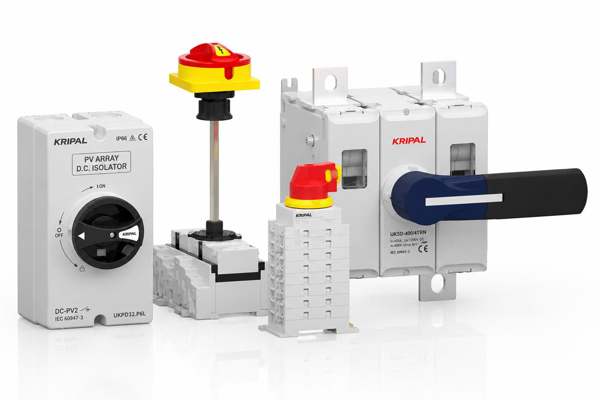
A battery energy storage system (BESS) contains multiple DC protection devices connected at different levels. Each device has to operate at the right moment. When two devices can respond to the same fault, the device closest to the fault should normally clear it first, while upstream protection remains in service.
This is the purpose of selective coordination. Rather than choosing each protection device independently, the devices must be evaluated as part of the complete protection chain.
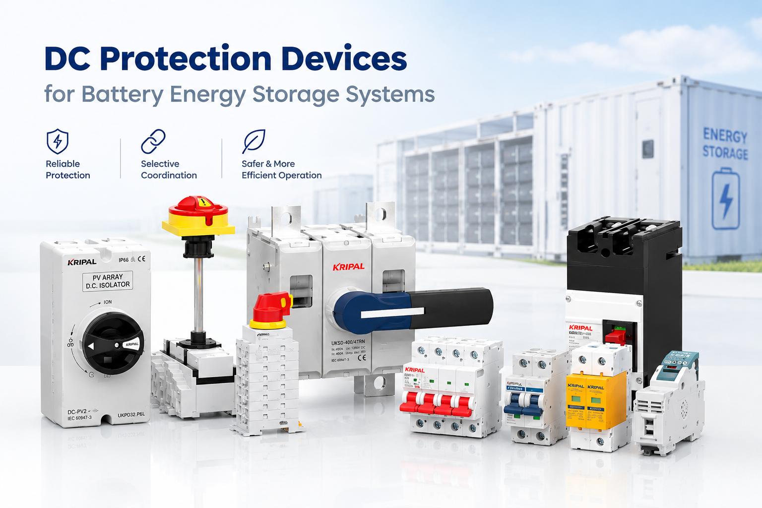
For DC battery storage systems, coordination is affected by the available fault current, device characteristics, interruption performance, conductor withstand capability, and the operating conditions of the battery. This guide explains the main principles used to coordinate DC protection devices from the string level to the container and inverter interface. Learn more about our full range of DC protection products or DC miniature circuit breakers for energy storage systems.
Why Coordination Is Different on DC Systems
Coordination on an AC system benefits from a natural current zero every half cycle. This assists arc extinction when a circuit breaker interrupts a fault. A DC circuit does not normally have this natural current zero. As a result, DC interruption can be more demanding, particularly at higher voltage and fault-current levels. The DC voltage rating, pole configuration, interruption capability, and application category of the protection device therefore need to match the actual system.
The available fault current also behaves differently from a typical transformer-fed AC system. In a battery system, the prospective fault current depends on factors such as battery internal impedance, interconnection impedance, the number of parallel cells or strings, battery chemistry, temperature, state of charge, and the configuration of the DC system.
For this reason, DC protection coordination should be based on the actual system configuration and manufacturer data rather than on a simple current-ratio rule.
What Does Selective Coordination Mean in Practice?
Selective coordination means that, for a defined range of prospective fault currents, the protection device intended to clear the fault operates before an upstream device.
For example, if a fault occurs inside one battery string, the string-level protection should clear the fault without unnecessarily disconnecting the entire rack or container.
The basic coordination requirement can be viewed in two ways:
-
✦
Fault Current Below Range
-
✦
Upstream Device Stays Closed
-
✦
Within Selective Range
-
✦
Downstream Clears Fault First
Selectivity may be total or partial. Total selectivity means the downstream device remains selective up to the maximum prospective fault current specified for the application. Partial selectivity means that selectivity is guaranteed only up to a defined current limit.
This distinction is important when evaluating a BESS protection scheme. A system that appears coordinated at a low test current is not necessarily coordinated across its complete prospective fault-current range.
Why the Battery Changes the Calculation
A transformer-fed system has a source impedance that contributes significantly to limiting prospective fault current. In a battery system, the available fault current is influenced by battery internal resistance and the complete DC circuit impedance.
A large battery installation can therefore provide substantial fault current. However, the actual value is not determined by battery capacity alone. Battery chemistry, state of charge, temperature, internal resistance, parallel configuration, conductors, busbars, contactors, and other components can all influence the available current.
State of charge can also affect battery electrical characteristics. Because the relationship between SOC and available fault current depends on the battery technology and operating conditions, a coordination study should consider the operating condition that produces the most demanding protection scenario, using battery manufacturer data where available.
The objective is not simply to assume that “full charge” always produces the highest fault current, but to identify and document the worst-case prospective fault-current condition for the actual system.
For BESS applications, the protection study should therefore establish the prospective fault current at each relevant protection level before selecting or setting the devices.
The Protection Devices That Usually Appear
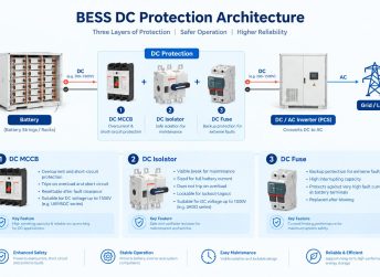
A container-scale BESS commonly contains several levels of DC protection. The exact architecture varies by system, but the protection chain can generally be considered from the individual string toward the rack, container DC bus, and inverter interface.
String and Module Level
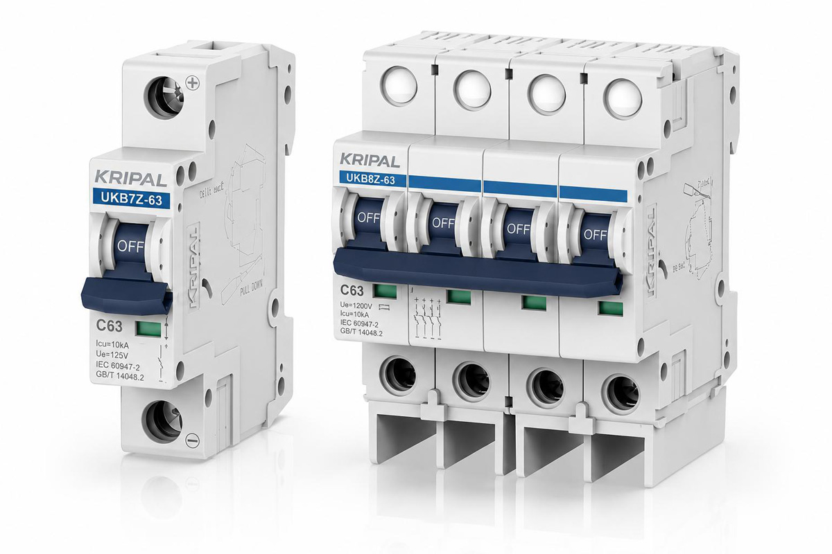
The innermost protection level protects an individual battery string or module group. Depending on the system architecture, this protection may use a DC miniature circuit breaker (MCB), fuse, or another dedicated DC protection device. Its purpose is to isolate a fault within the affected string while allowing the remaining strings and racks to continue operating where the system design permits it. Because this device is closest to the fault, its operating characteristics are particularly important for coordination with the rack-level protection.
When selecting a DC MCB, engineers should consider:
-
✦
Rated Current Selection
-
✦
DC Operating Voltage
-
✦
Breaking Capacity Rating
-
✦
Trip Characteristics
-
✦
Number of Poles
-
✦
Temperature & Conditions
-
✦
Manufacturer Data
Rack Level
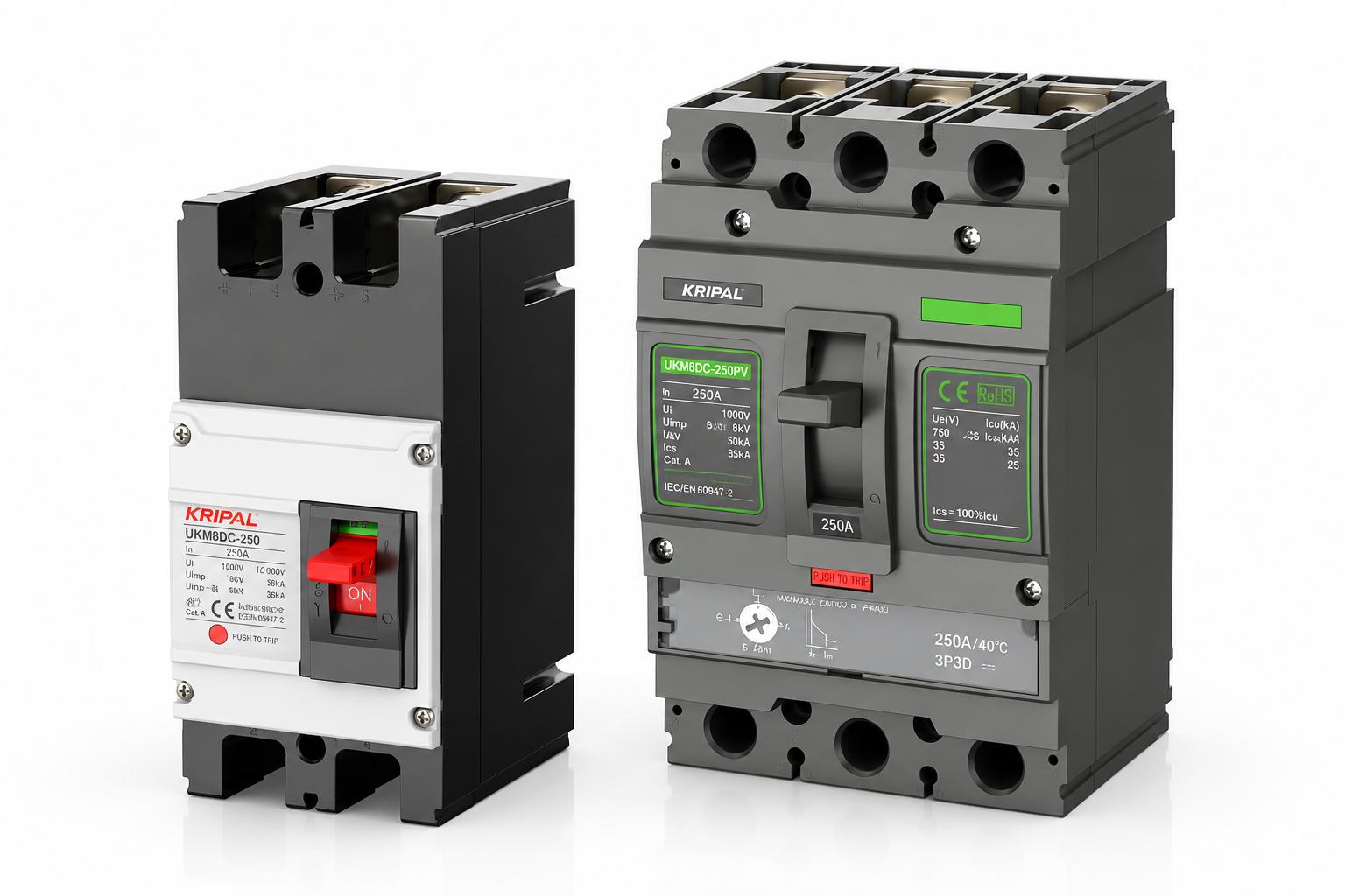
The rack-level protection device typically protects the conductors between the battery rack and the container DC bus.
A DC moulded case circuit breaker (MCCB) may be used at this level, depending on the system design.
This device has to coordinate with the protection below it while also maintaining selectivity with the larger protection device above it. It therefore sits in the middle of the coordination chain and has to satisfy requirements in both directions.
When selecting a rack-level DC MCCB, the relevant parameters include:
-
✦
Rated Current
-
✦
DC Voltage Rating
-
✦
Breaking Capacity
-
✦
Short-Time Withstand
-
✦
Adjustable Trip Settings
-
✦
Time-Current Curves
-
✦
Selectivity Tables
The exact current and voltage range should always be taken from the manufacturer’s current product datasheet rather than assumed from the frame size alone.
Container and Inverter Level
The outer protection level generally protects the main DC bus and the connection toward the PCS or inverter. This device is normally coordinated with the rack-level protection below it. Its settings should therefore not be selected only from the inverter’s rated current.
The available fault current at the container bus, the ratings of the downstream protection devices, and the manufacturer’s coordination data all need to be considered. A common mistake is to select the main breaker solely according to the inverter rating without checking whether it remains selective with the downstream rack devices.
Grading by Current
Current-based grading attempts to create separation between the operating ranges of downstream and upstream protection devices. The basic principle is straightforward: the downstream device should respond to the relevant fault while the upstream device remains outside its operating range for that same fault. However, rated-current values alone are not sufficient to prove selectivity.
Engineers should consider:
-
✦
Pickup Characteristics
-
✦
Instantaneous Trip
-
✦
Thermal Characteristics
-
✦
Tolerance Bands
-
✦
Prospective Fault Current
-
✦
Device Operating Curves
-
✦
Selectivity Tables
Setting the Operating Thresholds
Each protective device has an operating characteristic rather than one perfectly fixed trip point. For this reason, an upstream setting cannot simply be placed slightly above the nominal downstream rating and assumed to be selective. The tolerance of both devices and the actual fault-current range need to be considered. A coordination study should therefore compare the actual time-current characteristics and manufacturer data for the selected devices.
Do Not Rely on a Simple Current-Ratio Rule
A larger upstream breaker rating can help create separation between protection levels, but there is no universal rule that an upstream device must simply be twice the rating of the downstream device. The required relationship depends on the specific breaker or fuse characteristics, trip settings, prospective fault current, and manufacturer coordination information.
Where available, manufacturer selectivity tables and time-current curves should take precedence over a generic current-ratio rule. This is particularly important for DC systems, where interruption characteristics can differ significantly between device types and applications.
Grading by Time
Time grading introduces a deliberate delay into an upstream protection device so that the downstream device has an opportunity to clear the fault first. This approach can be useful when current-based discrimination alone cannot provide sufficient separation. However, the delay cannot be selected independently of the equipment’s short-circuit withstand capability.
The permissible delay may be limited by:
-
✦
Cable Thermal Withstand
-
✦
Busbar Withstand
-
✦
Equipment Short-Time Limits
-
✦
Breaker Short-Time Limits
-
✦
Fault-Current Magnitude
-
✦
Coordination Standards
The shortest applicable withstand limitation must be respected.
Where Time Grading Can Help
Time grading can be useful at higher levels of the protection system, where larger devices and conductors may have greater short-time withstand capability. It can also be useful where the ratings of adjacent protection devices are relatively close and current grading alone does not provide sufficient discrimination.
Where Time Grading Becomes Difficult
Time grading is less suitable for the inner protection levels, where the conductors and connected equipment may have limited short-circuit withstand capability. A protection delay should never be introduced simply to achieve coordination if the equipment cannot safely withstand the fault for that duration. The coordination study therefore needs to compare the proposed delay with the short-circuit withstand capability of the complete circuit.
Common Coordination Mistakes
The same coordination problems can appear across different BESS projects.
-
✦
Inverter-Only Rating Choice
-
✦
Capacity Equals Speed Error
-
✦
Fixed Current Ratio Reliance
-
✦
Ignoring Device Tolerances
-
✦
Single Operating Scenario
-
✦
Outdated Coordination Studies
Isolation Points in the Same Protection Chain
A DC switch-disconnector has a different role from a circuit breaker. Its primary purpose is safe isolation rather than automatic fault clearing. It must therefore be selected for the voltage, current, and switching duty of the application and must also withstand the relevant short-circuit conditions when required by the system design.
Important parameters can include:
-
✦
Rated Operational Voltage
-
✦
Rated Operational Current
-
✦
Utilization Category
-
✦
Short-Time Withstand
-
✦
Short-Circuit Making Duty
-
✦
Number of Poles
-
✦
Applicable Standards
The exact utilization category must be matched to the intended application. Categories such as DC-21B and DC-PV should not be treated as interchangeable; the applicable category should be confirmed from the product’s certification and datasheet.
Battery and Transformer Sources: What Changes?
| Property | Transformer-Fed System | Battery Energy Storage System |
|---|---|---|
| Main source impedance | Primarily influenced by transformer impedance | Influenced by battery and complete DC circuit impedance |
| Available fault current | Determined largely by source and system impedance | Influenced by battery configuration, internal impedance, and operating conditions |
| Natural current zero | Present in AC | Not normally present in steady DC |
| Operating condition | Usually less dependent on source state | May vary with SOC, temperature, and battery condition |
| Protection selection | Based on AC device characteristics | Requires DC-rated devices and application-specific data |
The important point is that a BESS coordination study cannot simply copy the assumptions used for an AC transformer-fed system. The source characteristics, DC interruption requirements, and actual protection-device characteristics all need to be considered.
Recording a DC Protection Coordination Study
A coordination study is only useful if the assumptions and results can be reviewed later. The record should include:
-
✦
Maximum System Voltage
-
✦
Prospective Fault Currents
-
✦
Battery Configuration Data
-
✦
Operating Condition Range
-
✦
Device Type & Ratings
-
✦
Specific Trip Settings
-
✦
Time-Current Curves
-
✦
Short-Circuit Limits
-
✦
Ambient Temp Limits
-
✦
Standards & Datasheets
Documenting the assumptions is almost as important as documenting the final settings.
When Should the Study Be Repeated?
The study should be reviewed whenever a change can affect the available fault current or protection characteristics. Examples include:
-
✦
Adding Battery Racks
-
✦
Changing Parallel Strings
-
✦
Reconfiguring DC Bus
-
✦
Changing Protection Devices
-
✦
Upgrading PCS / Inverter
-
✦
Modifying Busbar Layout
-
✦
Altering Conditions
Adding additional parallel battery capacity can increase the available fault current at parts of the DC system and may affect previously established coordination. The coordination study should therefore remain part of the commissioning and engineering documentation throughout the project lifecycle.
How to Confirm DC Protection Coordination
A coordinated BESS protection scheme is one in which each protection device has been evaluated against the devices around it and against the actual fault-current conditions of the system.
Before confirming the scheme, verify:
-
✦
Maximum System Voltage
-
✦
Prospective Fault Current
-
✦
Device Characteristics
-
✦
Relevant Trip Settings
-
✦
Selectivity Information
-
✦
Short-Circuit Limits
-
✦
Battery Operating Scenarios
-
✦
Total vs Partial Limits
The fault current at the container DC bus is particularly important because it can determine whether the outer protection remains coordinated with the rack-level devices. Recording that value together with the assumptions used in the study makes future system changes easier to evaluate.
Frequently Asked Questions
Selective coordination means that the protection device closest to a fault operates before upstream protection, within the specified fault-current range. This helps isolate only the affected section rather than unnecessarily disconnecting a complete rack or container.
Coordination requires comparing the prospective fault current with the time-current characteristics, trip settings, and manufacturer coordination data for the downstream and upstream devices. Rated-current ratios alone are not sufficient to prove selectivity.
No. A higher-rated breaker may provide greater separation between protection levels, but selectivity depends on the actual operating characteristics of both devices and the prospective fault current.
DC systems do not normally have the natural current zero present in AC systems. This makes DC interruption and arc extinction more demanding and means that DC voltage rating, interruption capability, and device application category require particular attention.
At minimum, the study should consider the maximum system voltage, prospective fault current at relevant locations, battery configuration and operating condition, protection-device ratings and settings, conductor and equipment withstand capability, and manufacturer coordination data.
Need Help Reviewing a DC Protection Scheme?
For a specific battery energy storage application, the protection scheme should be checked against the actual system configuration and manufacturer data.
Useful information for an initial technical review includes:
-
✦
Maximum DC Voltage
-
✦
Prospective Fault Current
-
✦
Protection Ratings & Types
-
✦
Operating Conditions
Need Custom DC Protection Scheme Engineering or Technical Support for Your BESS Projects?
Related Resources
Explore Knowledge Center >
Need a matching KRIPAL product?
Share voltage, quantity and destination. An engineer will reply with options and lead time.
