



Knowledge Center
Specifying a 1500 V DC Isolator for a Photovoltaic Array
Learn how to select a 1500V DC isolator for PV arrays. Check voltage ratings, pole config, enclosure IP rating and switching duty for solar photovoltaic systems.
 August 19, 2026
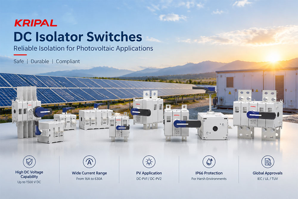
A DC isolator is an important component in a photovoltaic (PV) system. It provides a means of disconnecting a DC circuit for inspection, maintenance, or other procedures when used within its rated operating conditions and in accordance with applicable installation requirements.
Selecting an isolator for a 1500 V DC PV array involves more than checking the voltage printed on a product label. Rated operational voltage, current, switching duty, pole configuration, conductor size, short-circuit conditions, and enclosure protection must all be considered.
This guide explains the key specifications to review when selecting a DC isolator for a photovoltaic array, how to evaluate different frame sizes, and what to check before installation.
What Does a DC Isolator Do in a PV System?
A DC isolator is designed to disconnect a DC circuit under the conditions specified by its manufacturer. Depending on the product design and its ratings, a switch-disconnector may also be suitable for making and breaking current. However, a DC isolator should not automatically be treated as an overcurrent protective device. It does not replace a correctly selected fuse, circuit breaker, or other protective equipment where such protection is required.
A PV array can continue generating voltage whenever its modules are exposed to light. Opening an isolator therefore does not necessarily make every part of the array voltage-free.
Before maintenance, follow the site’s isolation and lockout/tagout procedures, observe the inverter and switch manufacturer’s instructions, and verify the condition of the relevant conductors with suitable test equipment. The installation must also comply with applicable electrical codes and safety requirements.
Isolation of Live Conductors
The required pole configuration depends on the system’s earthing arrangement, circuit design, and applicable installation rules. Depending on the system, both positive and negative conductors may need to be disconnected. Two-pole and four-pole DC isolators are available for different applications. The correct choice should be based on the system design and the manufacturer’s approved wiring diagram rather than on pole count alone.
Where an inverter includes a built-in DC switch, the designer should determine whether an additional external isolator is required. This depends on the applicable regulations, equipment instructions, installation layout, and maintenance requirements.
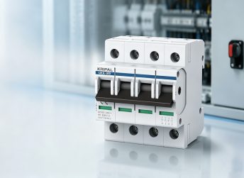
For more information, see KRIPAL’s PV DC isolator product range.
Loaded and No-Load Operations
The expected switching duty is an important part of isolator selection. A device operated frequently under load may experience different contact wear from one used mainly for isolation after the current has been interrupted elsewhere.
Manufacturers may publish separate figures for electrical endurance under specified switching conditions and for mechanical endurance. These figures describe different aspects of performance and should not be treated as interchangeable.
Stopping an inverter does not, by itself, prove that the current through an isolator is zero. The actual switching sequence must follow the equipment manufacturer’s instructions and the system’s approved operating procedure.
When comparing products, check:
Do not estimate service life from a single operation-count figure. Actual performance depends on the switching duty, installation conditions, and compliance with the manufacturer’s instructions.
The Ratings That Define a 1500 V DC Isolator
Several voltage and current values may appear on a DC isolator datasheet. Each describes a different characteristic, so the values must be read together.
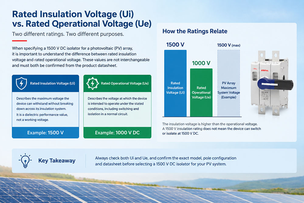
Rated Insulation Voltage (Ui) and Rated Operational Voltage (Ue)
Rated insulation voltage (Ui) relates to the insulation design of the device. Rated operational voltage (Ue) relates to the operating conditions under which the device is intended to function. These values are not interchangeable. A high insulation-voltage value does not, by itself, establish that a switch can safely make, break, or isolate a circuit at that same voltage.
For a PV system with a maximum design voltage of 1500 V DC, select a device whose specified operational voltage and approved configuration are suitable for that system voltage. Check the exact model’s datasheet and wiring diagram rather than relying on the product family name or a single voltage figure.
The PV array’s maximum voltage must also be calculated using the module specifications and the expected minimum temperature, following the applicable design rules. The nominal system voltage alone may not represent the highest voltage the isolator will experience.
Environmental conditions matter as well. Pollution degree, temperature, altitude, enclosure arrangement, and other installation conditions may affect the applicable ratings or selection requirements.
Before ordering, confirm that the selected model’s voltage rating applies to the intended pole configuration and wiring arrangement.
Utilization Category and PV Switching Duty
The utilization category indicates the type of electrical duty for which a switching device is designed and tested. It is an important part of the specification, not merely a product description. For PV applications, check the category and the relevant product standard stated by the manufacturer. KRIPAL publishes selected DC isolator models with DC-21B/PV2 markings; the suitability of a specific model must still be confirmed against the system’s switching duty and the applicable standard.
Do not assume that a general-purpose DC switch is suitable for every PV application simply because its voltage and current values appear adequate.
When reviewing a datasheet, confirm:
Understanding Other Electrical Ratings
A DC isolator datasheet may include impulse withstand voltage, short-time withstand current, making capacity, breaking capacity, and short-circuit making capacity. These values describe different conditions. They should not be combined into a single measure of how much fault current the device can safely interrupt.
| Rating | What to Check |
|---|---|
| Rated operational voltage | Whether the device is suitable for the maximum system voltage and intended switching duty |
| Rated current | Whether the current rating is adequate under actual installation and temperature conditions |
| Rated making capacity | The conditions under which the device can close onto a circuit |
| Rated breaking capacity | The current and conditions under which the device can interrupt a circuit |
| Short-circuit making capacity | The declared ability to close under specified short-circuit conditions |
| Short-time withstand current | The current the device can withstand for the stated duration and conditions |
| Rated impulse withstand voltage | The specified withstand capability against impulse overvoltage |
| Electrical and mechanical endurance | The declared endurance under the manufacturer’s stated test conditions |
A DC isolator should not be selected as the sole means of short-circuit protection unless the equipment is specifically designed and approved for that protective function. Check the prospective fault current and the protective-device coordination required for the installation.
Selecting the Correct Current Rating and Frame Size
The current rating is another key factor in DC isolator selection. KRIPAL offers DC isolator models for different current ranges, including models in the UKGD family. Available ratings, terminal arrangements, and voltage specifications vary by model. A frame’s published current range should not be interpreted as proof that every setting or configuration is suitable for every installation. The selected model must meet the required current rating under the specified conditions, including any applicable temperature or enclosure derating.
Comparing Representative KRIPAL UKGD Models
The following examples illustrate why the exact model code matters. They are not a substitute for the current formal datasheet.
| Model | Published Current Range | Published Voltage Information | Published Conductor Information |
|---|---|---|---|
| UKGD-250 | 100–250 A | 1000 V in the referenced product table | 70–120 mm² copper |
| UKGD-250G | 100–250 A | 1500 V in the referenced product table | 70–120 mm² copper |
| UKGD-325G | 100–325 A | 1500 V in the referenced product table | 185 mm² copper |
Source for these representative specifications: KRIPAL UKGD DC isolator product information. These published figures show why a buyer should not specify a product simply as a “250 A UKGD isolator.” The suffix and exact model configuration can affect the applicable voltage rating and terminal requirements.
For higher-current models, obtain the relevant datasheet and wiring drawing directly from the manufacturer. Confirm all electrical and mechanical ratings before including a model in the project specification.
Conductor Cross Section and Terminal Compatibility
The conductor size must be compatible with the isolator’s terminals. Check the permitted conductor material, cross-sectional area, number of conductors per terminal, terminal arrangement, and specified tightening torque. A conductor that is too large may not fit the terminal correctly. A conductor that is too small or improperly prepared may not be securely clamped.
Cable sizing must also account for current-carrying capacity, installation method, ambient temperature, grouping, voltage drop, and applicable electrical rules. The isolator’s terminal range is only one part of the cable-selection process.
Before installation, verify the cable preparation instructions and terminal torque specified for the exact model. Poor connections can lead to overheating and equipment damage.
Pole Configuration, Series Connections, and Wiring
Two-pole and four-pole DC isolators serve different circuit arrangements. Selecting the right configuration requires understanding the system voltage, conductor arrangement, earthing scheme, and the manufacturer’s approved wiring method.
Choosing Between Two-Pole and Four-Pole Versions
A two-pole device may be suitable where the circuit design requires switching of two conductors. A four-pole device may be used where additional poles are needed for an approved series arrangement or for separate circuits. However, pole count alone does not establish the voltage rating of the assembled circuit. The device must be connected according to the manufacturer’s diagram, and the declared operational voltage must apply to that exact configuration.
Why the Manufacturer’s Wiring Diagram Matters
Some DC isolator designs use poles in series to achieve a specified voltage capability. This arrangement is valid only where the manufacturer explicitly approves it and defines the required connections. Do not assume that connecting poles in series always doubles the voltage rating or that connecting them in parallel always produces a fixed reduction in voltage capability. The result depends on the device’s internal design, arc-control system, terminal arrangement, and approved configuration.
Incorrect wiring may compromise switching performance and electrical safety. Before energizing the circuit, check the terminal markings, the model-specific wiring diagram, and the required torque values.
The same principle applies when evaluating other DC switching devices: use the manufacturer’s declared ratings and approved connections rather than relying on a generic wiring rule.
Enclosure Protection and Outdoor Installation
The installation environment affects the choice of enclosure and the conditions under which the isolator can operate. A switch may be supplied as an open device for installation within suitable equipment, or as part of an enclosed assembly. The protection rating must be checked for the complete configuration being installed.
IP20 and IP66 Options
KRIPAL product information lists IP20 and IP66 options for selected DC isolator configurations. Do not assume that an open switch automatically has IP66 protection when placed inside any enclosure. The IP rating applies to the declared assembly and depends on the product version, enclosure, seals, cable entries, mounting, and installation instructions. Confirm the protection rating of the actual configuration specified for the project.
For outdoor PV applications, consider exposure to rain, dust, direct sunlight, temperature variation, and other environmental factors. Enclosure selection should reflect the installation location and the required level of protection.
Temperature, Derating, and Accessibility
An enclosed installation may have different thermal conditions from an open installation. Ambient temperature, ventilation, enclosure dimensions, and nearby heat sources can affect the current the device can carry continuously. Use the manufacturer’s ratings and any applicable derating guidance to confirm suitability.
Accessibility is equally important. The isolator should be installed where it can be operated and inspected in accordance with the design and safety requirements. Allow suitable clearance around the handle and ensure that the operating position is identifiable.
If an extension handle or door-coupling arrangement is required, confirm compatibility with the selected frame and enclosure.
Working Through a PV Isolator Selection Example
Consider a hypothetical PV installation with the following design requirements:
Confirm the Voltage Requirement
First, calculate the maximum PV array voltage using the module data and expected minimum temperature, in accordance with applicable design rules. Then check the isolator’s rated operational voltage and the manufacturer’s approved pole configuration. A model whose applicable operational voltage is only 1000 V DC must not be selected for a 1500 V DC circuit merely because its insulation-voltage figure is higher.
Check the Current Rating
The selected isolator must have an appropriate rated current for the circuit and installation conditions. A 220 A requirement falls within some published 250 A model ranges, but the exact model, configuration, and any required derating must be verified. For example, KRIPAL’s published product table distinguishes between UKGD-250 and UKGD-250G voltage specifications. The model suffix should therefore be confirmed rather than omitted from the purchase specification.
Verify the Conductor and Terminals
A 95 mm² copper conductor falls within the published 70–120 mm² conductor range shown for certain UKGD-250 models. This alone does not confirm suitability: check terminal details, cable type, installation method, tightening torque, and current-carrying requirements for the actual project.
Review Switching Duty and Fault Conditions
Confirm that the utilization category, making and breaking ratings, and switching duty are suitable for the PV circuit. The prospective short-circuit current and coordination with the circuit’s protective devices must also be assessed. Do not use a making-capacity figure as a substitute for a breaking-capacity or short-circuit protection assessment.
Confirm the Enclosure and Wiring Arrangement
Finally, verify the pole configuration, approved wiring diagram, enclosure protection, ambient conditions, and accessibility. The selected product should be specified by its complete model code and the ratings that apply to the intended configuration. Where any rating or connection detail is unclear, obtain confirmation from the manufacturer before ordering.
For model-specific details, consult the KRIPAL UKGD product information and request the latest technical datasheet for the exact model via our Contact Us page.
Where Should a DC Isolator Be Installed?
The installation location depends on the PV system design, inverter instructions, applicable regulations, and maintenance procedures. A DC isolator is commonly installed on the DC side of a PV system, between the array and the inverter, where it can serve the intended isolation function. However, its precise position and whether an external device is required must be determined for the specific installation.
Do not assume that installing a switch inside an inverter enclosure is always unacceptable, or that an external switch is always mandatory. Check the applicable requirements and the manufacturer’s instructions.
The isolator should be accessible for operation and maintenance, and its location should be clearly identified in the installation documentation.
For installation considerations, see KRIPAL’s guide to DC isolator switch installation for solar PV.
Common Specification Mistakes
Several mistakes can be avoided by checking the complete datasheet rather than selecting a product from one headline figure:
Where protection coordination or short-circuit selection is involved, review the complete system design rather than relying on the isolator’s current rating alone. KRIPAL’s related guide on DC MCB and DC fuse selection for solar PV protection provides additional context.
Frequently Asked Questions
Can a 1500 V DC isolator be used in every 1500 V PV system?
No. The exact model must be rated for the system’s maximum voltage and intended switching duty. The pole configuration, current rating, wiring arrangement, environmental conditions, and applicable installation requirements must also be checked.
Is rated insulation voltage the same as rated operational voltage?
No. Rated insulation voltage describes an insulation-related characteristic, while rated operational voltage relates to the device’s intended operating conditions. The insulation-voltage figure alone does not establish that the device is suitable for switching a circuit at that voltage.
Does opening a DC isolator make a PV array voltage-free?
Not necessarily. PV modules can continue producing voltage when exposed to light, and parts of the system may remain energized. Follow the approved isolation procedure and verify the relevant conductors before work begins.
Should a DC isolator be selected by current rating alone?
No. Voltage rating, switching duty, pole configuration, terminal compatibility, prospective fault current, enclosure conditions, and applicable standards are also important. All relevant ratings must be suitable for the intended application.
Can the poles of a DC isolator be connected in series to increase its voltage capability?
Only when the manufacturer explicitly permits the arrangement and provides the corresponding wiring diagram and ratings. Do not assume that series or parallel connections produce a universal change in voltage capability.
Does an IP66 enclosure guarantee that the installed isolator is suitable for outdoor use?
Not by itself. Confirm that the IP rating applies to the complete installed assembly and that the enclosure, seals, cable entries, temperature conditions, and mounting arrangement comply with the manufacturer’s instructions.
Conclusion: Confirm the Right DC Isolator Before Ordering
Specifying a 1500 V DC isolator for a photovoltaic array requires a complete assessment of voltage, current, switching duty, pole configuration, conductor size, fault conditions, and installation environment. The most important step is to verify the ratings for the exact model and approved wiring arrangement. Do not select a product solely because its name or insulation-voltage figure includes “1500 V.”
For a reliable specification, confirm the PV array’s maximum voltage, required current rating, conductor and terminal compatibility, switching category, short-circuit conditions, enclosure protection, and applicable installation requirements. Then match these requirements against the manufacturer’s current datasheet and wiring instructions.
KRIPAL provides DC isolator options for photovoltaic applications across different model and current ranges. For assistance with a particular installation, explore the KRIPAL PV DC isolator range and confirm the exact model code and technical ratings with our technical team via Contact Us before purchase.
Related Resources
Explore Knowledge Center >
Need a matching KRIPAL product?
Share voltage, quantity and destination. An engineer will reply with options and lead time.
