



Knowledge Center
Why a DC Circuit Breaker Cannot Be Replaced by an AC Breaker
Understand the technical differences between AC and DC circuit breakers. Learn about current-zero behavior, voltage ratings, polarity, and selection rules.
 August 14, 2026
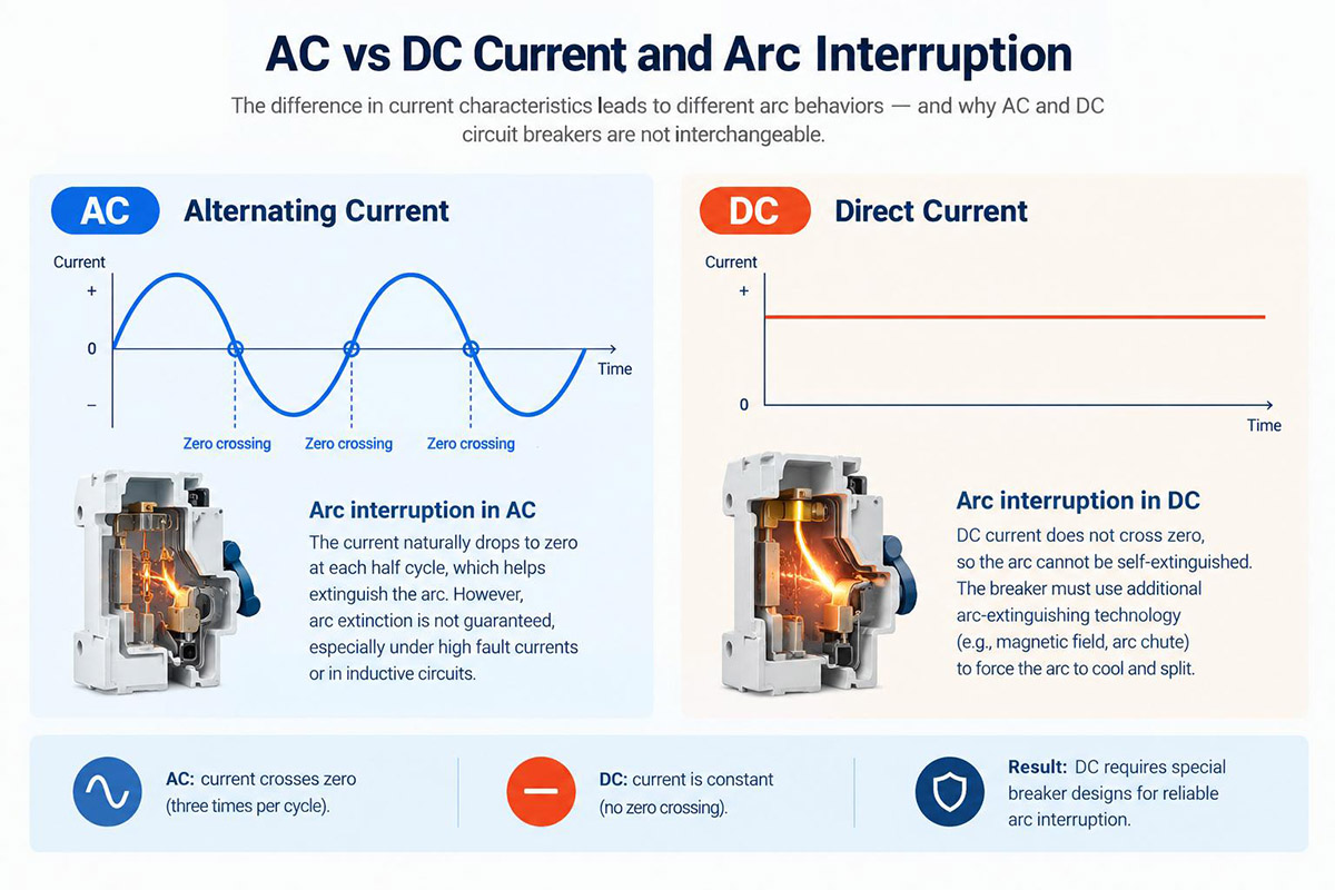
A 63 A AC breaker and a 63 A DC breaker may look similar, carry the same current rating, and fit the same rail. That does not make them interchangeable. A circuit-breaker selection must match the supply type, maximum working voltage, prospective short-circuit current, pole configuration, and the manufacturer’s specified application conditions.
On AC systems, current passes through zero twice per cycle—100 times per second at 50 Hz and 120 times per second at 60 Hz. These natural current zeros help an arc extinguish, although successful interruption also depends on the breaker’s design and the recovery voltage after the contacts open. DC circuits do not have periodic current zeros, so a DC-rated device must be designed to control and interrupt the arc under its specified DC conditions.
The Current Zero Problem
The behavior of an arc differs between AC and DC supplies. The comparison below summarizes the main design considerations; the ratings of any particular device must still be checked against its datasheet and wiring instructions.
Why Alternating Current Is Easier to Interrupt
In a 50 Hz AC system, current crosses zero 100 times per second; in a 60 Hz system, it crosses zero 120 times per second. Each current zero creates an opportunity for the arc to extinguish. Whether it stays extinguished depends on the contact system, arc-control design, and the transient recovery voltage across the opening contacts.
The arc chute helps split, lengthen, and cool the arc. A natural current zero can assist interruption, but it does not by itself guarantee that the arc will not restrike. The breaker must be rated for the applicable voltage and fault conditions.
Why Direct Current Has No Such Help
A steady DC circuit has no periodic natural current zero. Once an arc forms, the breaker must control it and create conditions under which the arc cannot be sustained. Contact separation, arc-chute design, magnetic blow-out where fitted, circuit voltage, fault current, and circuit inductance all affect interruption performance.
| Property | AC Breaker | DC Breaker |
|---|---|---|
| Arc extinction | Natural current zero can assist interruption; restrike performance still matters | Designed to interrupt DC current under declared DC conditions |
| Pole configuration | According to the circuit and product rating | May require a manufacturer-specified series pole arrangement |
| Voltage rating | Use declared AC working voltage and breaking ratings | Use declared DC working voltage, pole arrangement, and breaking ratings |
| Trip characteristics | Check complete time-current curve and applicable ratings | Check complete time-current curve and applicable DC ratings |
| Polarity | Usually not a DC current-direction issue | Some designs are polarity-sensitive; check model instructions |
| PV-string suitability | Do not assume suitability from an AC rating | Use only a device rated for specific PV or DC applications |
Why DC Arc-Control Design Matters
DC interruption can place demanding requirements on the contact system and arc-control structure. Some DC breakers therefore use larger or more specialized arc-control components, but physical size varies by product design, voltage rating, pole configuration, and breaking capacity.
A DC breaker is not suitable merely because its external dimensions or current rating resemble those of an AC breaker. The decisive evidence is the manufacturer’s DC rating for the exact model and pole configuration, not the enclosure size.
Why the Voltage Rating Changes With Pole Count
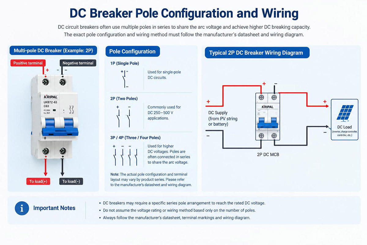
A DC voltage rating may depend on the specific pole configuration and the manufacturer’s prescribed series connection. The same number of poles does not guarantee the same DC rating across different product families.
Poles in Series to Share Arc Voltage
Some DC breaker designs use poles in series to interrupt higher DC voltages. The permitted voltage depends on the exact device, its tested pole arrangement, and the manufacturer’s wiring diagram. Never infer a DC voltage rating from pole count alone.
| Pole Configuration | Configuration Note | Application Note |
|---|---|---|
| 1P | Model-specific | Use only if exact datasheet permits system voltage |
| 2P | Model-specific | Check rated DC voltage and required series wiring |
| 3P | Model-specific | Check rated DC voltage and required series wiring |
| 4P | Model-specific | Check rated DC voltage and required series wiring |
Where the Substitution Error Becomes Concrete
For example, a two-pole AC breaker marked 400 V AC must not be assumed suitable for a 500 V DC string. AC and DC ratings are established for different operating conditions, and an AC voltage figure does not establish the device’s DC interruption capability.
Some devices carry both AC and DC ratings, with different limits for voltage, pole arrangement, and breaking capacity. If the datasheet does not explicitly provide a suitable DC rating for the intended configuration, do not assume the device is qualified for DC use.
Series Wiring Has Its Own Rules
Where a manufacturer specifies multiple poles in series to achieve a particular DC rating, follow the exact connection diagram and all polarity instructions. Check the device’s insulation and clearance requirements as well as the system voltage.
Incorrect series wiring can compromise arc control and expose contacts or insulation to conditions outside the device’s rating. Do not assume voltage will divide evenly between poles under fault interruption; use only a configuration explicitly approved by the manufacturer.
Polarity and Non-Polarity in DC Breakers
Two breakers with similar current and voltage markings may have different requirements for current direction. This matters particularly in circuits where current can flow in either direction, but the exact requirement must be confirmed from the manufacturer’s documentation.
Two Designs That Look Identical
Some DC breaker designs are polarity-sensitive, while others are designed for specified bidirectional applications. Appearance alone does not identify the design. Check the model’s polarity markings, wiring diagram, and declared suitability.
- A polarity-sensitive breaker is designed for a specified current direction. Its arc-control mechanism may rely on the intended magnetic blow-out direction, so reversing the connection can impair interruption performance where prohibited by the manufacturer.
- A breaker described as non-polarized may be suitable for current in either direction within its declared ratings and wiring conditions. Confirm bidirectional suitability in the datasheet rather than relying on the term alone.
Why Storage Systems Need the Second Type
This is relevant to battery energy storage systems because charging and discharging can reverse current direction through a circuit. Before using a breaker in a bidirectional circuit, verify that the exact model is approved for the required current direction, voltage, fault level, and connection arrangement.
The wider picture of how devices are combined in a storage system is covered in our guide on BESS DC protection with MCCBs, isolators, and fuses. That guide covers the layering of devices rather than individual components.
Reading a DC Breaker Datasheet
A DC breaker datasheet should be checked against actual circuit conditions. Key items include rated working voltage, rated current, rated short-circuit breaking capacity, trip characteristics, polarity requirements, and applicable utilization categories.
The Columns That Decide Suitability
| Parameter | What It Tells You | What to Check |
|---|---|---|
| Rated working voltage | Permitted operating voltage for the stated configuration | Match maximum system voltage and approved pole arrangement |
| Rated current | Continuous current under stated reference conditions | Apply manufacturer derating and check cable or load requirements |
| Rated DC breaking capacity | Fault current the device can interrupt under stated conditions | Compare with prospective short-circuit current at installation point |
| Time-current / trip characteristics | Response to overloads and short circuits | Check full curves, inrush current, and required disconnection time |
| Polarity / current direction | Permitted current direction and connection arrangement | Confirm suitability for unidirectional or bidirectional duty |
| Product standard / category | Product requirements and duty declared | Confirm correct standard and category for the device type |
The Instantaneous Trip Band
The instantaneous trip range is only one part of a thermal-magnetic breaker’s time-current behavior. For example, a stated range such as 7–15 times rated current must be checked against the manufacturer’s curve, load inrush characteristics, prospective fault current, and required disconnection time.
A trip characteristic not suited to the load can cause nuisance operation or fail to provide required fault protection. Selection should be based on the complete time-current curve and applicable installation rules, not a single multiplier. Learn more about how these components operate in our article on thermal-magnetic breaker operation.
Reading Beyond the Ampere Figure
How datasheet parameters relate to string protection is detailed in our guide to DC isolators, DC MCBs, and DC fuses.
Derating in Real Installations
Published ratings are based on defined reference conditions. Ambient temperature, installation method, adjacent devices, and altitude may affect usable current. Apply the correction factors specified by the manufacturer for the exact device.
Temperature Inside the Enclosure
A 63 A breaker does not necessarily carry 63 A under every condition. A sealed enclosure exposed to direct sun can become much hotter than the surrounding air. Thermal-magnetic breakers are affected by internal temperature and surrounding conditions. Check manufacturer ambient-temperature limits and coordinate the selected rating with cable and load requirements.
Grouping and Altitude
- Breakers mounted side by side share heat; manufacturers publish grouping factors that reduce usable current.
- Altitude affects insulation performance and heat dissipation. Apply altitude corrections as specified for the selected product.
- A breaker selected too close to load current may have insufficient usable capacity after derating. Always check the final corrected rating.
Where This Bites Hardest
Derating is especially critical in sealed outdoor enclosures exposed to high ambient temperatures and solar heating. Use actual installation conditions and manufacturer guidance rather than assuming fixed generic corrections.
Where DC Protection Sits in a Solar or Storage System
DC protection is coordinated across the system, with each device selected for its circuit location and fault conditions. Fuses, circuit breakers, switch disconnectors, and surge protective devices perform distinct functions and are not interchangeable.
Four Positions, Four Jobs
| Location in System | Possible Device(s) | Primary Function |
|---|---|---|
| PV string circuit | DC fuse or suitably rated DC circuit breaker | Overcurrent protection where required by design rules |
| Array/output circuit | DC MCCB or rated protective device; switch disconnector | Protection and isolation (switch disconnectors provide isolation only) |
| Between array & inverter | DC switch disconnector and/or DC SPD | Isolation and surge protection based on topology rules |
| Battery / storage circuit | DC-rated circuit breaker/fuse; isolator | Overcurrent protection and isolation; verify bidirectional duty |
Why One Device Rarely Covers Everything
A system often requires separate devices for overcurrent protection, load switching, isolation, and surge protection. A string fuse or appropriately rated DC MCB provides overcurrent protection; a switch disconnector provides isolation or switching only within declared limits and cannot clear short circuits.
DC surge protection should be installed according to system topology, installation standards, protection zones, and manufacturer instructions.
Choosing Between a Fuse and a Breaker
Fuses and circuit breakers both interrupt fault currents, but their time-current and current-limiting characteristics differ. Compare specific fuse and breaker datasheets, including breaking capacity and prospective fault current, rather than assuming one is always faster.
A breaker can be reset after fault investigation, whereas a fuse must be replaced. Choice depends on system design, selectivity, fault current, cable protection, and maintenance strategy. Explore our comparison of DC isolators and DC circuit breakers for additional guidance.
Device Families Used in DC Protection
The following examples illustrate three KRIPAL product families relevant to DC protection. Always confirm ratings, connections, and limits against current datasheets before specifying devices.
Miniature Breakers for String Level Protection
The UKB7Z-63 DC miniature circuit breaker is available in 1P, 2P, 3P, and 4P versions, with current options from 6 A to 63 A and C characteristic curves. Rated working voltage is 250 V DC for 1P (T = 5 ms) and 500 V DC for 2P (T = 4 ms), with a rated breaking capacity of 6,000 A (6 kA). Do not infer 750 V DC or 1000 V DC ratings for 3P or 4P versions without explicit datasheet confirmation. Power electrodes must be wired correctly per terminal markings to ensure proper fault interruption.
Moulded Case Breakers for Array Level Protection
The UKM32-250PV DC MCCB features a 250 A frame with current options from 63 A to 250 A. It includes 3P and 4P versions rated at 750 V DC and 1000 V DC respectively, with an insulation voltage of 1000 V DC and an impulse withstand voltage of 8 kV. Ultimate short-circuit breaking capacity (Icu) options include 20 kA (N-type) and 50 kA (H-type), with thermomagnetic tripping mechanisms.
| Parameter | 3-Pole UKM32-250PV | 4-Pole UKM32-250PV |
|---|---|---|
| Frame rated current | 250 A | 250 A |
| Rated current options | 63, 80, 100, 125, 160, 200, 250 A | 63, 80, 100, 125, 160, 200, 250 A |
| Rated working voltage (Ue) | DC 750 V | DC 1000 V |
| Rated insulation voltage (Ui) | DC 1000 V | DC 1000 V |
| Impulse withstand voltage (Uimp) | 8 kV | 8 kV |
| Service breaking capacity (Ics) | 100% of Icu | 100% of Icu |
| Ultimate breaking capacity (Icu) | 20 kA (N-type) / 50 kA (H-type) | 20 kA (N-type) / 50 kA (H-type) |
| Mechanical life | 10,000 operations | 10,000 operations |
| Electrical life | 2,000 operations | 1,000 operations |
| Trip method | Thermomagnetic | Thermomagnetic |
Isolators and Switch Disconnectors
Isolation and fault interruption are separate functions. The UKGD63 is a 1500 V DC isolator rated for DC-21B and PV2 categories with a thermal current of 63 A. Larger frame isolators span 250 A to 630 A at 1500 V DC, with making capacities up to 6300 A. Always confirm load and no-load operating cycle requirements against specific model datasheets.
Surge Protection at the DC Entry
DC SPDs are selected using parameters including maximum continuous operating voltage (Uc) and voltage protection level (Up). Follow manufacturer installation and coordination guidelines closely.
Why the Substitution Error Persists
Substitution errors persist because AC and DC devices look virtually identical from the outside despite having drastically different internal arc-control mechanisms.
Physical Similarity
- Devices share external dimensions and mounting profiles.
- Ampere ratings are printed prominently, whereas voltage and pole rules sit in fine print.
- Some AC breakers list limited DC ratings at lower voltages, which users misread as full DC compliance.
The Delayed Failure
An incorrectly selected device may function normally under everyday load conditions but fail catastrophically when attempting to interrupt a fault. Uncontained arcs can cause severe equipment destruction or personnel injury.
Testing and Commissioning DC Protection
Even a correctly specified device will fail if wired improperly. Verification before energization is essential.
What to Verify Before Energization
- Confirm pole series wiring strictly matches engineering drawings.
- Check polarity markings against intended current directions on battery storage circuits.
- Verify terminal torque values to prevent high-resistance connection hot spots.
- Confirm and record adjustable trip settings.
What to Record
Commissioning documentation should detail model numbers, pole arrangements, wiring configurations, trip settings, and test parameters to support ongoing maintenance and fault investigations.
A Specification Checklist for DC Protection
Use this technical checklist when evaluating DC protective devices for your installation:
Electrical Inputs
- System maximum working voltage, including maximum PV string voltage under cold-temperature design conditions.
- Pole count and the manufacturer’s approved series connection, where applicable.
- Load current, conductor requirements, and ambient-temperature, grouping, or altitude derating factors.
- Prospective short-circuit current at the installation point compared against the device’s rated DC breaking capacity.
Application Inputs
- Whether current flows in one or both directions, and whether the exact model is approved for bidirectional duty.
- Whether the required function is overcurrent protection, load switching, isolation, or surge protection.
- Enclosure thermal environment and manufacturer derating guidance.
- Applicable product standards, safety regulations, and project codes.
Frequently Asked Questions
AC and DC circuits have different arc-interruption characteristics. AC current naturally crosses zero during each cycle, which assists arc extinction. DC current does not have periodic natural zero crossings, so a breaker must be specifically rated and designed to interrupt DC current at the intended voltage and fault level.
Not necessarily. Some DC circuit breakers use multiple poles connected in series to achieve a specified DC voltage rating. The permitted voltage depends on the exact model and its manufacturer-approved wiring configuration. Always check the datasheet rather than estimating voltage from pole count.
The wiring configuration directly affects the breaker’s ability to interrupt a DC fault safely. Some models also have strict polarity or current-direction requirements. Follow the manufacturer’s terminal markings and wiring diagram for the exact model and application.
A DC MCB is commonly used in lower-current branch circuits, while a DC MCCB is often selected for higher-current circuits or applications requiring different frame sizes and protection options. The appropriate choice depends on rated voltage, current, breaking capacity, trip characteristics, and installation conditions.
Check the maximum system voltage, operating current, prospective short-circuit current, required DC breaking capacity, pole configuration, current direction, and installation conditions. Confirm that the exact breaker model is rated for the intended application and follows the required wiring arrangement.
The DC breaking capacity is the maximum fault current that a breaker is rated to interrupt under specified test and operating conditions. It must be suitable for the prospective short-circuit current at the installation point, at the applicable DC voltage and pole configuration.
Getting the Device Right the First Time
DC circuits do not have periodic natural current zeros, so a DC-rated breaker must use a design tested for specified interruption duties. Current rating alone is insufficient: maximum working voltage, breaking capacity, pole configuration, current direction, and environmental factors all dictate suitability. Never substitute an AC breaker for a DC breaker without verified manufacturer ratings.
Choosing the Right DC Protection for Your Application
Before specifying a DC circuit breaker, confirm system working voltage, fault currents, required breaking capacity, pole arrangements, current directions, and installation environments. Review product datasheets and wiring schematics carefully. For technical assistance with solar PV, battery storage, or industrial DC installations, contact KRIPAL with your project parameters.
Need Technical Selection Support for Your DC Circuit Breakers & Protection Systems?
Related Resources
Explore Knowledge Center >

Need a matching KRIPAL product?
Share voltage, quantity and destination. An engineer will reply with options and lead time.
