


 Search
Knowledge Center
Reversing Contactor Guide: Forward and Reverse Motor Control Wiring
Learn how reversing contactors change motor direction, wire forward/reverse circuits, and combine mechanical and electrical interlocking safely.
 June 20, 2026
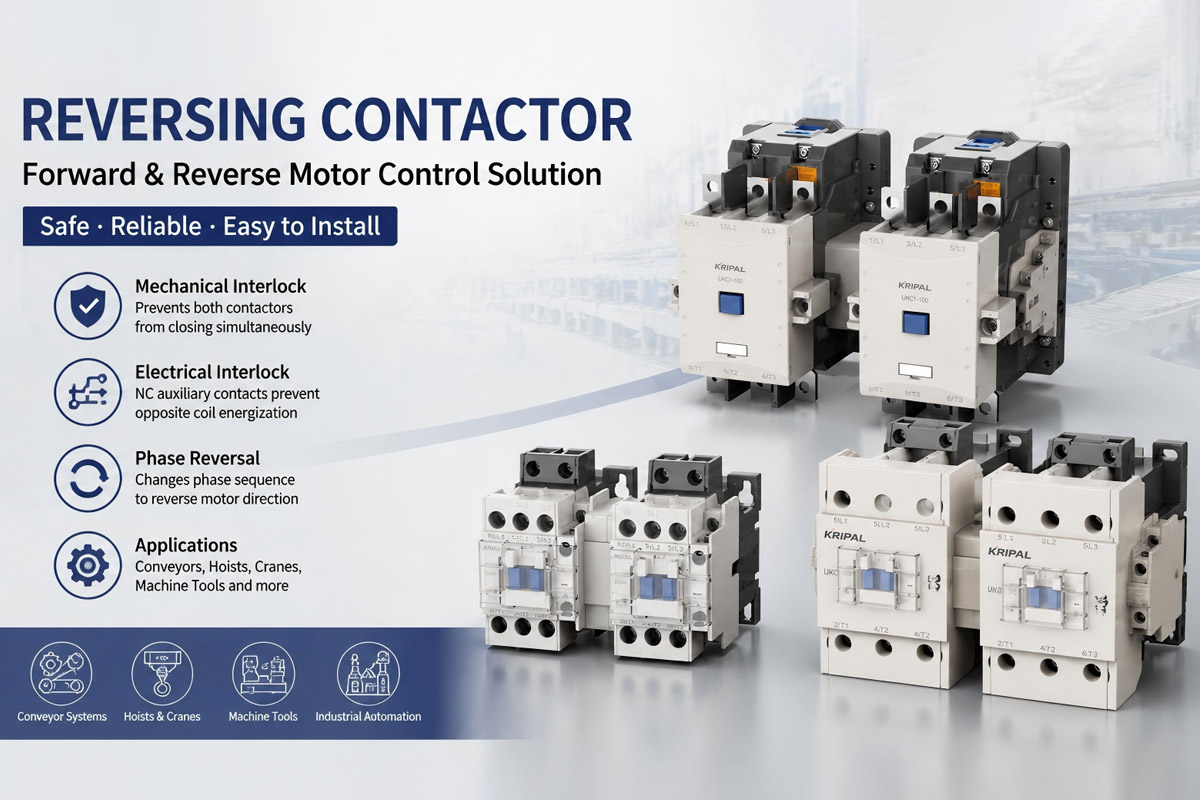
A reversing contactor is a motor control device designed to change the rotation direction of three-phase motors by switching the phase sequence supplied to the motor terminals. It is widely used in industrial applications such as conveyors, hoists, cranes, machine tools, and automated production equipment where forward and reverse operation is required.
Unlike a standard contactor that only switches power ON and OFF, a forward reverse contactor assembly uses two contactors working together with mechanical and electrical interlocking systems to safely control motor direction.
When a reversing contactor is incorrectly wired or both contactors close simultaneously, a phase-to-phase short circuit can occur in the power circuit, resulting in extremely high fault current and possible damage to the contactors. Proper interlocking design is therefore essential for safe and reliable motor reversing applications.
This guide explains how reversing contactors work, the difference between mechanical and electrical interlocking, and the basic wiring principles for forward and reverse motor control systems.
The Phase Reversal Principle
The rotation direction of a three-phase induction motor is determined by the phase sequence supplied to the motor stator windings.
With a standard phase sequence:
L1 → L2 → L3
the motor rotates in one direction.
By exchanging any two phases, the rotating magnetic field changes direction, causing the motor to rotate in the opposite direction.
A reversing contactor assembly achieves this by using two contactors with different output wiring configurations:
Forward Contactor
The forward contactor connects the supply phases to the motor in the normal sequence:
- L1 → U
- L2 → V
- L3 → W
Reverse Contactor
The reverse contactor swaps two phases:
- L1 → W
- L2 → V
- L3 → U
This phase reversal changes the motor rotation direction without changing the motor itself.
A complete reversing starter normally includes:
- Two power contactors
- Mechanical interlock
- Electrical interlock using auxiliary contacts
- Motor overload protection
- Control circuit with forward, reverse, and stop commands
The two contactors must never close simultaneously. If both contactors operate at the same time, the reversing starter power circuit can create a direct phase-to-phase short circuit.
What Is a Mechanical Interlock in a Reversing Contactor?
A mechanical interlock is a physical safety mechanism installed between the forward and reverse contactors. Its purpose is to prevent both contactors from closing at the same time under normal operating conditions.
In a reversing contactor assembly, the mechanical interlock connects the two contactor mechanisms together. When one contactor closes, the interlock physically blocks the opposite contactor from moving into the closed position.
For example:
- When the forward contactor is energized, the mechanical interlock prevents the reverse contactor from closing.
- When the reverse contactor is energized, the forward contactor is blocked.
The mechanical interlock works independently of the control circuit. Even if both contactor coils receive a command signal due to a control fault, the physical mechanism prevents simultaneous contact closure.
However, like any mechanical component, the interlock should be correctly installed and regularly inspected, especially in applications with frequent reversing cycles.
Factory-Assembled vs Field-Assembled Reversing Contactors
There are two common approaches for building a reversing contactor system.
Factory-Assembled Reversing Contactors
Factory-assembled reversing units are supplied with:
- Two matched contactors
- Pre-installed mechanical interlock
- Correct phase connection
- Factory-tested assembly
For example, the Kripal UKC1-R reversing contactor series integrates the mechanical interlock and contactor arrangement into a complete reversing solution, reducing installation time and wiring errors.
Field-Assembled Reversing Starters
A reversing starter can also be built by combining:
- Two standard contactors
- An external mechanical interlock kit
- Additional control wiring
This method provides flexibility but requires careful installation. Incorrect alignment of the mechanical interlock or incorrect phase wiring can compromise the protection function.
What Is Electrical Interlock in a Reversing Contactor?
While the mechanical interlock provides physical protection, an electrical interlock adds another layer of control protection by preventing the opposite contactor coil from being energized.
The electrical interlock is typically achieved by using normally closed (NC) auxiliary contacts from each contactor.
The basic principle is:
- The forward contactor NC auxiliary contact is placed in series with the reverse contactor coil.
- The reverse contactor NC auxiliary contact is placed in series with the forward contactor coil.
When the forward contactor energizes:
- Its main contacts close.
- Its NC auxiliary contact opens.
- The reverse contactor coil circuit is interrupted.
- The reverse contactor cannot energize.
The same process occurs when the reverse contactor operates.
This electrical interlocking method creates a redundant safety layer together with the mechanical interlock.
Forward and Reverse Contactor Control Logic
A standard three-wire reversing control circuit normally includes:
- Stop pushbutton (NC)
- Forward start pushbutton (NO)
- Reverse start pushbutton (NO)
- Forward contactor coil
- Reverse contactor coil
- Auxiliary holding contacts
- Electrical interlocking contacts
The forward and reverse contactors use cross-connected NC auxiliary contacts to prevent both coils from being energized through the control circuit.
Wiring a Reversing Contactor Step by Step
Correct wiring is essential for the safe operation of a reversing contactor system. A complete reversing starter contains two separate circuits:
- Power circuit — carries the three-phase motor current.
- Control circuit — controls contactor operation and interlocking logic.
Both circuits must be correctly configured to prevent phase faults and unintended motor operation.
Power Circuit Wiring of a Reversing Contactor
The power circuit contains two parallel paths from the three-phase supply to the motor.
The typical wiring sequence is:
Forward Contactor Connection
The forward contactor connects the incoming phases to the motor in the standard sequence:
- L1 → U
- L2 → V
- L3 → W
This produces the normal motor rotation direction.
Reverse Contactor Connection
The reverse contactor changes the phase sequence by exchanging two phases:
- L1 → W
- L2 → V
- L3 → U
This causes the motor to rotate in the opposite direction.
The motor overload relay is normally installed in series with the motor circuit to provide overcurrent protection during operation.
Control Circuit Wiring of a Forward Reverse Motor Control System
A standard reversing contactor control circuit uses a three-wire control method.
The basic wiring sequence is:
- Connect the control supply to the Stop pushbutton normally closed (NC) contact.
- From the Stop pushbutton output, connect the control supply to both Forward and Reverse start circuits.
- The Forward start pushbutton (NO) energizes the forward contactor coil through the Reverse contactor NC auxiliary contact.
- The Reverse start pushbutton (NO) energizes the reverse contactor coil through the Forward contactor NC auxiliary contact.
- Each contactor uses its own NO auxiliary contact as a holding or seal-in circuit.
- Both contactor coils return to the control supply through their A2 terminals.
This arrangement ensures that once one direction is selected, the opposite contactor cannot be energized through the control circuit.
Pushbutton Interlocking for Manual Reversing Stations
For manually operated reversing systems, additional protection can be achieved through pushbutton interlocking.
Forward and reverse pushbuttons may include:
- One NO contact for the start command
- One NC contact for disabling the opposite direction circuit
For example:
When the Forward button is pressed:
- The Forward NO contact closes and energizes the forward contactor.
- The Forward NC contact opens and prevents the reverse coil circuit from being energized.
This provides an additional control-level electrical interlock before the contactor coils receive power.
However, pushbutton interlocking should not replace the primary mechanical and electrical interlocking built into the reversing starter.
A properly designed system combines:
- Mechanical interlock between contactors
- Electrical interlock using auxiliary contacts
- Control logic protection from pushbuttons or PLC systems
Reversing Contactor Interlocking Methods Comparison
Multiple interlocking methods are commonly combined in industrial motor control systems to improve operational reliability.
| Method | Operating Principle | Failure Mode | Kripal Implementation |
|---|---|---|---|
| Mechanical interlock | Physical barrier prevents both armatures from closing | Wear on interlock mechanism after millions of operations | Factory installed on all UKC1-R series |
| Electrical interlock | NC auxiliary contacts break opposite coil circuit | Welded auxiliary contact keeps circuit closed | Dual auxiliary contacts on UKC1-85R and UKC1-100R models |
| Pushbutton interlock | NC contact on pushbutton opens opposite direction circuit | Operator holds both buttons simultaneously | Standard on Kripal reversing starter enclosures |
| PLC logic interlock | Software prevents both outputs from energizing | Program scan race condition during direction change | Recommended time delay of 50ms between direction changes |
Common Applications of Reversing Contactors
Reversing contactors are widely used in industrial equipment where motors must operate in two directions.
Conveyor Direction Control
Conveyor systems often require forward and reverse movement for:
- Material handling
- Loading and unloading
- Position adjustment
- Maintenance operations
A reversing contactor allows operators or PLC systems to control conveyor direction through a simple motor starter arrangement.
The Kripal UKC1-R series provides a compact solution for three-phase motor reversing applications.
Hoist and Crane Up/Down Control
Electric hoists and lifting equipment commonly use reversing contactors for:
- Up movement
- Down movement
- Position adjustment
These systems usually combine:
- Reversing contactor
- Overload protection
- Control pendant
- Motor brake control
Because lifting equipment involves frequent direction changes, reliable interlocking is especially important.
Machine Tool Spindle Reversing
Machine tools such as:
- CNC lathes
- Milling machines
- Tapping machines
often require rapid motor reversing during machining operations.
Applications with frequent reversing cycles require contactors selected according to the correct utilization category, such as AC-3 or AC-4 depending on the starting and reversing conditions.
Product Recommendation: Kripal UKC1-R Reversing Contactor Series
For industrial motor reversing applications, the Kripal UKC1-R series provides a factory-assembled reversing contactor solution.
Key features include:
- Integrated mechanical interlock
- Factory-assembled contactor arrangement
- Reduced wiring time
- Reliable forward and reverse motor control
- Suitable for industrial three-phase motor applications
Compared with field-assembled reversing starters, factory-built reversing contactors reduce installation complexity and minimize the risk of incorrect mechanical alignment or phase wiring.
See the UKC1-100R reversing contactor and related models in the reversing contactor category.
Conclusion
A reversing contactor is a reliable solution for controlling forward and reverse operation of three-phase motors. By combining phase reversal wiring with mechanical and electrical interlocking, reversing starters provide safe and efficient motor direction control for industrial applications. Correct selection, wiring, and installation are essential for preventing phase faults and ensuring long service life. For applications requiring reliable forward and reverse motor control, factory-assembled reversing contactor solutions such as the Kripal UKC1-R series provide a practical and efficient option.
Frequently Asked Questions
Q: What happens if both forward and reverse contactors close at the same time?
If both contactors close simultaneously, the reversing starter power circuit can create a phase-to-phase short circuit. The resulting fault current may damage the contactor contacts before the upstream protection device disconnects the circuit. Mechanical and electrical interlocking are designed to prevent this condition during normal operation.
Q: What is the difference between a reversing contactor and a normal contactor?
A standard contactor controls motor ON/OFF operation, while a reversing contactor uses two contactors and an interlocking system to control both forward and reverse motor rotation.
Q: Can I build a reversing starter from two standard contactors?
Yes. Two standard contactors can be assembled into a reversing starter by adding:
- Mechanical interlock kit
- Electrical interlocking wiring
- Correct phase reversal connections
Factory-assembled reversing contactors simplify installation and reduce wiring errors.
Q: Why does my reversing contactor hum loudly in one direction?
A loud hum from the contactor coil usually indicates the armature is not seating fully. On a reversing assembly, this can happen if the mechanical interlock is partially engaged from the opposite contactor not fully opening. Check that the interlock mechanism moves freely and that both contactors return to the fully open position when de-energized. Dirt on the magnet faces or a deformed shading ring on the AC coil magnet can also cause humming. Clean the magnet faces with a dry cloth and replace the contactor if the shading ring is cracked.
Q: Do I need a time delay between forward and reverse commands?
A short delay is commonly applied between stopping one direction and starting the opposite direction. The required delay depends on:
- Contactor characteristics
- Motor inertia
- Control system design
- Application requirements
PLC-controlled systems often include a timer to prevent rapid direction changes.
Q: How do you wire a reversing contactor?
A reversing contactor requires two contactors connected with opposite phase sequences.
The forward contactor uses the normal phase order: L1-U, L2-V, L3-W
The reverse contactor swaps two phases: L1-W, L2-V, L3-U
Electrical and mechanical interlocks must also be installed to prevent both contactors from operating simultaneously.
Related Resources
Explore Knowledge Center >
Need a matching KRIPAL product?
Share voltage, quantity and destination. An engineer will reply with options and lead time.
