



Knowledge Center
Detecting and Preventing DC Arc Faults in Solar PV Systems
Understand solar PV DC arc fault origins, AFCI detection methods, and how DC MCBs, MCCBs, and isolators reduce electrical fire risks in solar arrays.
 August 17, 2026
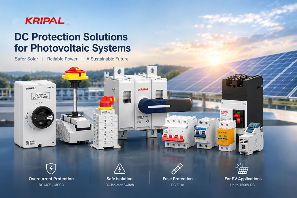
A DC arc can persist because direct current does not naturally pass through zero as AC does. Under suitable circuit conditions, an arc may continue until the fault is interrupted or the conditions sustaining it change. In photovoltaic (PV) systems, early detection, correct equipment selection, and sound installation practices all help reduce the risk of fire and equipment damage.
This guide explains where DC arcs can originate, how arc-fault detection works, and how system design and protection devices contribute to risk reduction. Product ratings mentioned below are examples only; always confirm the exact values, application limits, and approvals in the datasheet for the selected model.
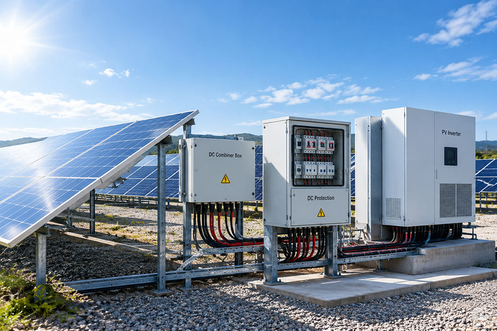
Where DC Arc Faults Originate
An arc requires an electrical gap and conditions that allow current to continue flowing across it. PV modules can produce voltage whenever they receive light, so parts of a PV circuit may remain energized during daylight even when the inverter is not operating. Common causes include poor connections, damaged conductors, and insulation faults.
Loose and Corroded Connections
A loose or corroded terminal can increase contact resistance and create localized heating. If the connection separates or becomes unstable, arcing may occur. PV connectors deserve particular attention because they are assembled in the field and depend on compatible components, correct preparation, and the specified crimping tool. A joint can appear mechanically secure while still having an electrically poor connection.
Damaged Cable and Insulation
Crushed cables, abrasion against sharp edges, excessive bending, UV exposure, moisture ingress, or animal damage can compromise a conductor or its insulation. Depending on the damage and circuit conditions, this may lead to a series arc, a parallel arc, an earth fault, or a short circuit. Not every damaged cable creates a high-resistance point, so the fault type should be assessed rather than assumed.
Series Arcs and Parallel Arcs
A series arc occurs in a current-carrying path, such as at a broken or deteriorated connection. Its current may remain near the normal operating current or even be lower, so conventional overcurrent protection may not trip. A parallel arc occurs between conductors at different electrical potentials; its fault current depends on the available source current, circuit impedance, array configuration, and fault path. The two fault types can produce different electrical signatures and require suitable detection and protection measures.
What Makes an Arc Detectable
Arc-fault detection systems analyze electrical signals associated with arcing, which may include high-frequency components, changes in current or voltage, and patterns over time. A simple magnitude threshold is generally insufficient because normal inverter operation and switching events can also produce electrical noise.
High-Frequency Signals and Inverter Noise
An arc can generate rapid changes in current and voltage that contribute high-frequency content to the circuit. However, inverters and other power-electronic equipment also generate switching noise. A suitable detector must distinguish fault-related signals from normal operating conditions and other disturbances; detection performance depends on the system design, operating conditions, and validated detection method.
Arc-fault detection may be integrated into an inverter or implemented through other appropriately designed and approved system components. It is not correct to assume that all systems require a separate string-level detector, or that a separate detector will always provide greater sensitivity. The suitable method and location depend on the system architecture, applicable requirements, and equipment design.
Arranging a System to Reduce Arc Risk
Detection helps identify a fault after it begins, while good installation practices reduce the likelihood of creating the fault in the first place. Inspection, correct component selection, and compliance with local electrical requirements are essential parts of a PV safety plan.
Connection Practice
Use the connector manufacturer’s specified tools and procedures, and verify the completed crimp and connection as required by the instructions. Do not mate connectors from different manufacturers unless their compatibility has been explicitly confirmed by the manufacturers and applicable requirements. Similar appearance does not guarantee compatible dimensions, materials, or electrical performance.
Cable Routing and Protection
Support cables to prevent movement, abrasion, and strain at terminals. Observe the cable manufacturer’s minimum bending radius and use suitable conduit, trunking, or mechanical protection where damage is likely. Protection coordination should be based on the system design, conductor ratings, available fault current, and applicable installation rules; do not assume a protective device will clear every type of arc fault.
Devices and Their Role in DC Fault Protection
DC MCBs, DC MCCBs, fuses, and switch-disconnectors serve different purposes. Correctly selected overcurrent protection can interrupt specified overload or short-circuit currents within the device’s ratings. It does not, by itself, guarantee detection or interruption of every series or parallel arc. Dedicated arc-fault detection and interruption functions must be provided where required by the applicable code, standard, or system design.
String Protection: DC MCBs and Fuses
At the string level, a DC miniature circuit breaker (DC MCB) or appropriately rated fuse may protect conductors and equipment against specified overcurrent conditions. Some DC MCB models are published with a rated short-circuit breaking capacity up to 6 kA, and certain trip curves specify an instantaneous operating range such as 7–15 times rated current. These values are model- and curve-specific: they must not be treated as universal ratings or as an arc-detection threshold. Confirm the DC voltage rating, polarity or connection requirements, trip characteristic, breaking capacity, and suitability for the PV circuit before selection.
Array-Level Protection: DC MCCBs
For higher-current circuits, a DC molded-case circuit breaker (DC MCCB) may be suitable when its voltage rating, current range, breaking capacity, and application conditions match the system. For example, a product family may include a 250 A frame with adjustable settings across a stated range and variants for different DC voltages. Do not apply a family-level range to every model: confirm the precise voltage, current setting range, and short-circuit rating in the relevant datasheet. Breaking capacity describes the maximum prospective fault current the device is rated to interrupt under specified conditions; it is not a direct measure of the arc energy released during a fault.
Where a DC Isolating Switch Belongs
A DC switch-disconnector provides a designated isolation point when correctly selected and operated in accordance with the manufacturer’s instructions. Whether it is suitable for load breaking, and whether it provides a visible contact gap, depends on its design, ratings, and applicable standard. Utilization categories must be copied exactly from the relevant product documentation: DC-21B and DC-PV2 are distinct categories and must not be used interchangeably. Likewise, a 1500 V DC rating or PV-specific category must be confirmed for the exact model and intended application.
Important safety note: Opening an isolator does not necessarily make PV modules or all upstream conductors de-energized. Follow the manufacturer’s procedure and applicable safe-isolation rules, and have work performed by qualified personnel.
| Location / Function | Typical Device or System | What It Contributes |
|---|---|---|
| PV string/circuit overcurrent protection | DC MCB or DC fuse | Interrupts specified overcurrent faults within its ratings; does not guarantee series-arc detection. |
| Higher-current array or feeder circuit | DC MCCB | Provides overcurrent and short-circuit protection when correctly rated and coordinated. |
| Designated maintenance isolation point | DC switch-disconnector | Provides an isolation function according to its rating, design, and operating instructions. |
| Arc-fault detection and interruption | AFCI function or suitable detection system | Identifies and initiates a response to defined arc-fault conditions when required and properly applied. |
What Happens After an Arc Event
After a suspected arc event, isolate the affected circuit using the approved procedure and have the installation assessed by a qualified person before re-energization. Document the event and inspect connectors, conductors, insulation, terminals, and associated equipment. Heat discoloration, melting, or carbonization may help identify the affected area, but visual appearance alone cannot reliably establish the root cause.
The investigation should consider whether the evidence is consistent with a series arc, a parallel arc, an earth fault, a loose connection, or another failure mode. Do not clean or replace parts before documenting relevant evidence when it is safe and appropriate to do so. Determine and correct the underlying cause before returning the system to service.
For related product selection, link this section to KRIPAL’s relevant DC MCB, DC MCCB, DC isolator, and DC fuse pages, as well as any published guide comparing their functions. Ensure that linked material accurately explains which faults each device is designed and rated to interrupt.
Frequently Asked Questions
What causes DC arc faults in solar PV systems?
Common contributing factors include loose or incompatible connections, poor crimps, damaged cables, degraded insulation, mechanical stress, and environmental exposure. Correct installation and regular inspection help reduce risk.
What is the difference between a series arc and a parallel arc?
A series arc occurs along a current-carrying path, while a parallel arc occurs between conductors at different electrical potentials. Fault current and detection characteristics depend on the circuit and fault conditions.
Can a DC MCB detect a series arc fault?
A conventional DC MCB provides overcurrent protection according to its design and ratings; it should not be assumed to detect a series arc. Where required, a suitable arc-fault detection and interruption function must be provided.
What is the role of a DC isolator in a PV system?
A correctly rated DC switch-disconnector provides a designated isolation point. It is not an arc detector, and opening it does not necessarily de-energize PV modules or every upstream conductor.
How can installers reduce the risk of DC arc faults?
Use compatible connectors and the specified crimping tools, route and support cables correctly, protect wiring from mechanical damage, follow manufacturer instructions, verify protection ratings, and comply with applicable electrical requirements.
Conclusion
DC arc-fault risk is reduced through a combination of sound installation, suitable detection where required, and correctly rated DC protection devices. Use compatible connectors, protect cables from damage, and verify every device against the actual circuit voltage, current, and fault conditions. DC MCBs, DC MCCBs, fuses, and isolators have distinct roles; none should be presented as a substitute for a dedicated arc-fault detection function where one is required.
For PV projects, select products using the exact model datasheet and applicable standards rather than relying on a family-level rating or a general rule. After any suspected arc event, identify and correct the underlying cause before the circuit is returned to service.
Technical Disclaimer
This article is for general technical information only and does not replace project-specific engineering, applicable electrical codes, or manufacturer instructions. Product ratings and application suitability vary by model and configuration; verify all parameters in the current official datasheet before selection or installation. Electrical work should be carried out by qualified personnel using approved safety procedures. Need customized project advice? Contact our engineering team.
Related Resources
Explore Knowledge Center >
Need a matching KRIPAL product?
Share voltage, quantity and destination. An engineer will reply with options and lead time.
