


 Search
Knowledge Center
What is a Mechanical Interlock for Contactors?
Learn how mechanical interlocks prevent simultaneous contactor closure in reversing starters and transfer switches. Compare electrical vs mechanical interlocks.
 June 24, 2026
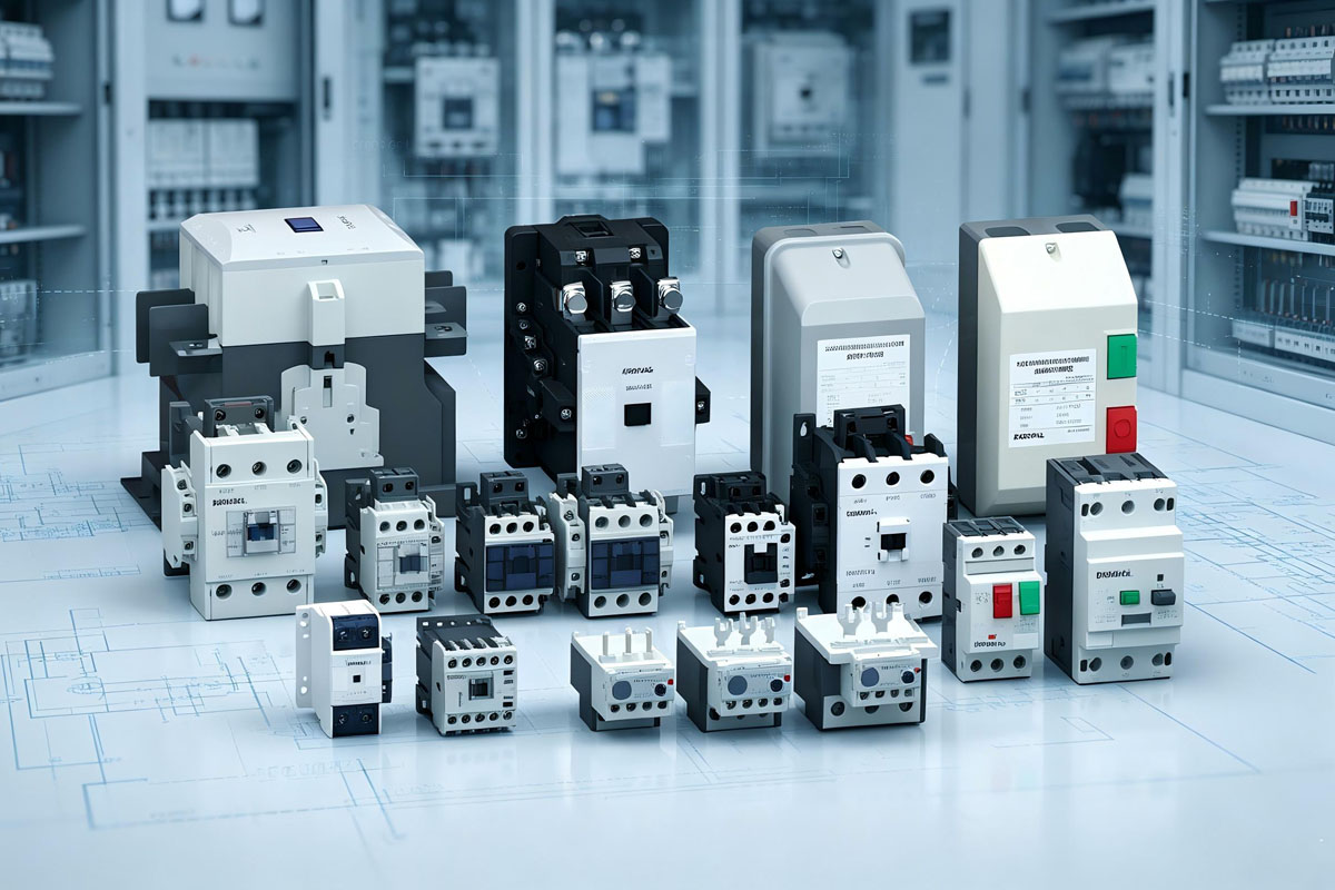
Two contactors controlling opposite operating conditions, such as forward and reverse motor rotation or two alternative power sources, must never close at the same time. If both contactors operate simultaneously, the result can be a phase-to-phase short circuit, severe arc flash, damaged contactors, and possible equipment failure. A mechanical interlock for contactors prevents this dangerous condition by physically blocking one contactor from closing while the other contactor is already engaged.
Mechanical interlocks are widely used in:
- Reversing motor starters
- Contactor-based transfer switches
- Dual power supply systems
- Industrial control panels
Unlike electrical interlocking, which depends on auxiliary contacts and control wiring, a mechanical interlock provides a physical safety barrier independent of the control circuit. For contactor assemblies, mechanical interlocking solutions are commonly designed according to the requirements of IEC 60947-4-1, the international standard covering contactors and motor-starters.
Why Electrical Interlocking Alone Is Not Enough
A standard reversing starter normally uses two contactors with an electrical interlock. Each contactor coil circuit includes a normally closed (NC) auxiliary contact from the opposite contactor.
When one contactor energizes:
- Its auxiliary contact opens
- The opposite contactor coil circuit is interrupted
- Both contactors are prevented from closing under normal conditions
However, electrical interlocking relies on electrical components and wiring integrity. Certain faults can bypass this protection.
Common failure conditions include:
- A welded auxiliary contact that fails to open the opposing coil circuit
- Incorrect control wiring during installation or maintenance
- A damaged auxiliary contact block
- External control faults that energize both coils simultaneously
A mechanical interlock adds an independent physical protection layer. Because it operates through the contactor mechanism itself, it does not rely on coil voltage, auxiliary contacts, or control wiring.
Mechanical Interlock vs Electrical Interlock
Although both systems prevent simultaneous contactor operation, they work in different ways.
In industrial motor control applications, the highest level of protection is achieved by using both electrical and mechanical interlocking together. The electrical interlock prevents the blocked contactor coil from remaining energized, while the mechanical interlock prevents physical simultaneous closing.
Electrical Interlock
Uses NC auxiliary contacts wired in series with the opposite contactor coil. When one contactor energizes, its NC contact opens and prevents the opposing coil from receiving power.
Effective under normal conditions but vulnerable to welded contacts, wiring errors, and control circuit faults.
Mechanical Interlock
Uses a physical blocking mechanism installed between two compatible contactors. When one contactor closes, the interlock prevents the opposite contactor from reaching the closed position.
Provides protection independent of coil voltage, auxiliary contacts, and control wiring integrity.
| Feature | Electrical Interlock | Mechanical Interlock |
|---|---|---|
| Working principle | Uses NC auxiliary contacts in control circuits | Uses a physical blocking mechanism |
| Depends on | Control wiring and auxiliary contacts | Mechanical movement of contactors |
| Protection against wiring faults | Limited | Yes |
| Protection against welded auxiliary contacts | Limited | Yes |
| Installation position | Control circuit | Between contactors |
| Recommended application | Standard control protection | Additional physical safety protection |
How a Mechanical Interlock Works
A mechanical interlock is a mechanical linkage installed between two compatible contactors. The interlock connects with the operating mechanism of each contactor. When one contactor closes, the interlock moves into a blocking position and prevents the opposite contactor from moving into the closed position.
The mechanism may use different designs depending on the manufacturer, including:
- Rocker mechanisms
- Sliding blocks
- Mechanical locking levers
The working principle remains the same:
- Only one contactor can reach the closed position at any time.
The KRIPAL UKC1 series uses a modular interlock accessory designed for compatible contactors of the same frame size. The interlock fits between two contactors and provides mechanical blocking protection against simultaneous operation.
Mechanical Interlock Wiring Diagram
In a typical reversing contactor application, two types of interlocking are used together:
1. Electrical Interlock Wiring
The normally closed auxiliary contact of each contactor is connected in series with the opposite contactor coil.
Example:
- Forward contactor NC auxiliary contact → Reverse coil circuit
- Reverse contactor NC auxiliary contact → Forward coil circuit
When the forward contactor energizes, its NC auxiliary contact opens and prevents the reverse contactor coil from energizing.
2. Mechanical Interlock Installation
The mechanical interlock is installed between the two contactors.
Its function is independent of the control circuit:
- Forward contactor closes → reverse contactor physically blocked
- Reverse contactor closes → forward contactor physically blocked
This creates two independent protection layers.
Reversing Contactor Application
A reversing starter uses two contactors to change the rotation direction of a three-phase motor by swapping two phases.
Typical connection:
Forward contactor:
- L1 → U
- L2 → V
- L3 → W
Reverse contactor:
- L1 → W
- L2 → V
- L3 → U
If both contactors close simultaneously, the phase arrangement creates a phase-to-phase short circuit. A mechanical interlock ensures that even if both contactor coils receive power due to an electrical fault, only one contactor can physically close. The blocked contactor may produce a humming sound because its coil is energized but the mechanism cannot complete the closing movement. This indicates a control fault that should be investigated.
For reversing motor starters, KRIPAL recommends using both:
- Electrical interlocking
- Mechanical interlocking
The mechanical interlock prevents simultaneous closure, while the electrical interlock prevents unnecessary coil heating.
Transfer Switch Application
Mechanical interlocks are also used in contactor-based transfer switching systems where two power sources supply a common load.
Examples include:
- Utility power and generator power
- Two independent AC supplies
- Emergency backup systems
The mechanical interlock ensures that only one source contactor can close at a time, preventing accidental connection between two power supplies. However, large automatic transfer switch (ATS) systems may use dedicated transfer mechanisms rather than standard contactor interlocks. The correct solution depends on the system design and switching requirements.
Mechanical interlocks are especially useful in applications where equipment may remain inactive for long periods because they rely on simple mechanical operation without electronic components.
Installation and Testing Requirements
A mechanical interlock should be installed according to the manufacturer’s instructions.
General installation steps include:
Mount two compatible contactors in the correct position.
Install the mechanical interlock between the contactors.
Verify that the contactors cannot close simultaneously.
Complete electrical interlock wiring.
Test operation before connecting the load.
Recommended testing:
- Manually operate each contactor and confirm the opposite contactor is blocked.
- Energize each coil separately with the load disconnected.
- Verify that electrical interlocking prevents both coils from remaining energized.
Common Mechanical Interlock Problems
Can a mechanical interlock fail?
Although mechanical interlocks are reliable devices, damage can occur due to:
- Physical impact
- Incorrect installation
- Broken internal components
- Contactor misalignment
Signs of damage include:
- Cracked interlock housing
- Visible mechanical damage
- Both contactors moving toward the closed position simultaneously
A damaged mechanical interlock should be replaced immediately.
Frequently Asked Questions
Q: Can I retrofit a mechanical interlock to existing contactors?
Only if the contactor series supports compatible interlock accessories. KRIPAL UKC1 interlocks are designed for compatible UKC1 contactors of the same frame size.
Q: Does a mechanical interlock eliminate the need for an electrical interlock?
No. The recommended solution is to use both. The mechanical interlock prevents simultaneous physical closing, while the electrical interlock prevents the blocked contactor coil from remaining energized.
Q: What happens if one contactor welds closed?
If one contactor welds closed, the mechanical interlock prevents the opposite contactor from closing. However, the welded contactor must be replaced because the interlock cannot repair damaged contacts.
Q: Can three contactors be mechanically interlocked?
Most standard mechanical interlocks are designed for two contactors. For multi-contactor systems, such as complex motor control applications, use application-specific solutions combining electrical interlocking and mechanical protection where required.
Upgrade Your Panel Safety with KRIPAL Mechanical Interlocks
A reliable contactor interlocking system is essential for safe motor control and power switching applications. If your reversing starter or transfer system relies only on electrical interlocking, adding a mechanical interlock provides an additional physical safety barrier.
KRIPAL mechanical interlocks are designed for integration with compatible contactor series, including:
- UKC1
- UKC2
- UKC5
Explore KRIPAL mechanical interlock solutions or contact our technical team for application support.
Related Resources
Explore Knowledge Center >
Need a matching KRIPAL product?
Share voltage, quantity and destination. An engineer will reply with options and lead time.
