



Knowledge Center
How to Select DC Cables for Solar PV Strings: Current, Voltage and Temperature
Comprehensive solar PV DC cable sizing guide: calculate ampacity, derating, voltage drop, cold-weather Voc max, UV resistance, and DC protection coordination.
 August 22, 2026
Photovoltaic cable selection involves more than choosing a conductor with a sufficient current rating. In a solar PV installation, cables operate under changing temperatures, continuous DC voltage, sunlight exposure and outdoor environmental conditions. A cable that meets the current requirement but has an unsuitable voltage rating, insulation system or sheath construction may deteriorate prematurely or create an electrical safety risk.
Selecting the correct cable requires checking several factors together: current-carrying capacity, voltage drop, maximum system voltage, operating temperature, environmental resistance and termination compatibility.
This guide explains how to select DC cables for solar PV strings, what electrical and environmental conditions affect cable performance, and which installation and component-selection issues deserve attention.
Sizing the Conductor
The conductor size is determined by the calculated design current, installation conditions and allowable voltage drop. These checks should be considered together rather than selecting a cable from its nominal current rating alone.
Current Carrying Capacity
The first step is to establish the design current of the PV circuit. For a photovoltaic string, the module short-circuit current (Isc) provides an important starting point. The calculation must also account for the number of parallel strings and the applicable design factors required by the electrical installation standard.
The required cable ampacity must then be checked against the actual installation conditions. Ambient temperature, cable grouping, conduit installation, ventilation and the cable’s maximum permitted conductor temperature can all affect its current-carrying capacity.
For example, a cable installed in an exposed rooftop tray may experience different thermal conditions from the same cable installed in a ventilated indoor enclosure. Where several loaded cables are installed together, mutual heating can further reduce the available current capacity.
A cable selected using an unrestricted free-air current rating may therefore be unsuitable when installed in a hot conduit or grouped cable route.
The temperature of a cable installed on or close to a sun-exposed roof can also be significantly higher than the surrounding air temperature. The actual temperature depends on roof material, solar exposure, ventilation and installation arrangement. Appropriate temperature correction factors should be applied when determining the required conductor size.
The final selection must satisfy the applicable current-carrying capacity requirements after all relevant correction factors have been considered.
Voltage Drop Along the String
Voltage drop is another important factor in PV cable sizing. Excessive voltage drop increases electrical losses and reduces the voltage available at the inverter input.
For a two-conductor DC circuit, the voltage drop is calculated using the total positive and negative conductor path. If the cable route is 30 metres one way, the electrical loop length is normally 60 metres.
For a simplified copper conductor calculation:
Where:
The voltage drop percentage is:
For final engineering calculations, use the conductor resistance at the relevant operating temperature and the cable manufacturer’s published data where available.
A voltage drop of around 1% may be adopted as a design target for certain PV cable routes, but it is not a universal regulatory limit. The acceptable value depends on the project design, total DC-side losses, cable route and applicable local requirements.
If the calculated voltage drop is too high, increasing the conductor cross-sectional area can reduce resistance and improve system efficiency.
A Practical Cable Sizing Checklist
| Design Parameter | What Needs to Be Checked |
|---|---|
| PV module Isc | Module short-circuit current |
| Parallel strings | Number of strings connected in parallel |
| Design current | Applicable current factors and local requirements |
| Installation method | Free air, conduit, tray or bundled installation |
| Ambient temperature | Relevant temperature correction factors |
| Cable length | Total positive and negative conductor path |
| Voltage drop | Project-specific allowable voltage drop |
| Protection | Cable ampacity and protective device coordination |
Why Voltage Rating Counts on Direct Current
The DC voltage rating of a photovoltaic cable must be suitable for the maximum system voltage. An AC voltage rating cannot automatically be treated as an equivalent DC rating.
AC and DC cable ratings are established under different test conditions and depend on the insulation system, cable construction and applicable product standards. The fact that an AC waveform passes through zero does not mean its insulation is unloaded between voltage peaks. Cable insulation remains subject to electrical stress throughout operation.
For this reason, a cable marked with a 1,000 V AC rating should not automatically be assumed suitable for a 1,000 V DC photovoltaic system.
IEC 62930 specifically addresses single-core cables for the DC side of photovoltaic systems, with rated DC voltage up to and including 1.5 kV between conductors and between conductor and earth. The standard specifies requirements for cable construction and performance, including insulation and sheath properties.
Where applicable, EN 50618 is another important reference for photovoltaic cables, including the H1Z2Z2-K cable designation. The actual cable specification and manufacturer’s declared ratings must always be checked before installation.
The Cold Temperature Case
One of the most important voltage checks in a solar PV system occurs during cold weather.
The open-circuit voltage (Voc) of a PV module generally increases as its cell temperature decreases. Consequently, the maximum string voltage may occur on a cold, clear morning rather than during normal daytime operation.
The maximum string voltage is determined by the number of modules connected in series and the temperature-corrected open-circuit voltage of each module.
A simplified calculation is:
The temperature correction should use the module manufacturer’s published Voc temperature coefficient and the lowest expected cell temperature at the installation location.
For example, where the manufacturer’s Voc temperature coefficient is expressed as a negative percentage per degree Celsius, the module’s open-circuit voltage increases as the temperature falls below the reference temperature.
The calculated maximum string voltage must remain within the permitted voltage limits of the PV modules, cables, inverter and all connected DC components.
Selecting a cable or protection device based only on standard test conditions (STC) can therefore result in an inadequate voltage rating under actual cold-weather conditions.
The same maximum-system-voltage check should be applied to DC circuit breakers, isolators, fuses and other equipment connected to the PV string.
What the Environment Does to the Cable
A photovoltaic cable installed outdoors must withstand sunlight, temperature variation, moisture and mechanical exposure over its expected service life.
The conductor carries electrical current, while the insulation and outer sheath provide electrical separation and environmental protection. Cable selection must therefore consider the complete cable construction rather than conductor material and cross-sectional area alone.
Sunlight and Ultraviolet Resistance
Ultraviolet radiation can gradually degrade polymer insulation and sheath materials that are not designed for prolonged outdoor exposure.
Depending on the material and exposure conditions, degradation may cause discoloration, surface cracking, reduced flexibility and deterioration of the protective layer.
PV cables intended for exposed outdoor installations should have documented resistance to UV radiation and weathering in accordance with their applicable product standard and manufacturer’s specification.
IEC 62930 includes weathering and UV-resistance requirements for cables within its scope. EN 50618 also provides a relevant specification framework for photovoltaic cables.
A cable intended only for protected indoor or conduit installation should not be substituted for an exposed PV cable unless its manufacturer confirms that the construction is suitable for the intended environment.
Temperature Cycling and Mechanical Movement
Outdoor PV cables experience repeated heating and cooling as environmental temperatures and electrical loads change. These variations can cause expansion and contraction of the cable materials.
Wind movement, inadequate cable support and excessive mechanical loading can also place stress on cable glands, connectors and terminal connections.
To reduce these risks, cable installation should follow the manufacturer’s requirements for minimum bending radius, fixing intervals and mechanical support.
Cable supports should be arranged to prevent excessive movement and avoid transferring mechanical loads to electrical terminals. Particular attention should be paid to cable sections close to connectors, enclosures and equipment terminals.
The following table summarizes the main cable properties that should be considered during PV system design:
| Cable Property | Why It Matters | What to Verify |
|---|---|---|
| Conductor size | Determines current capacity and voltage drop | Design current after derating and voltage drop |
| DC voltage rating | Must suit the maximum calculated PV system voltage | Manufacturer’s declared DC rating |
| Insulation and sheath | Provide electrical and environmental protection | Applicable cable standard and material specification |
| Temperature rating | Determines permitted conductor operating temperature | Cable datasheet and installation conditions |
| UV and weather resistance | Supports long-term outdoor performance | Documented weathering and UV resistance |
| Flexibility | Affects installation and termination | Conductor class and minimum bending radius |
Connections, Terminations and Common Substitution Errors
A correctly sized cable does not guarantee a reliable PV installation. Connectors, terminals and protective devices must also be suitable for the conductor and the electrical conditions of the system.
Poorly made connections can create increased contact resistance, localized heating and premature component failure. Termination quality should therefore receive the same attention as conductor sizing.
Crimped Connections
PV connectors rely on correctly prepared and crimped conductors to establish a reliable electrical and mechanical connection.
The crimping tool, contact and conductor must be compatible with the connector manufacturer’s requirements. Using an unsuitable tool or incorrect crimping die can produce a connection with inadequate contact pressure or mechanical retention.
PV connectors should be used in combinations that have been tested and approved by the connector manufacturer. Connectors from different manufacturers should not be assumed to be interchangeable simply because their dimensions or locking mechanisms appear similar.
Differences in contact geometry, materials, manufacturing tolerances and sealing arrangements can affect electrical resistance, mechanical retention and environmental protection.
IEC 62852 provides safety and testing requirements for connectors used in DC photovoltaic systems. Its scope should not be interpreted as general approval for mixing connector products from different manufacturers.
Where compatibility has not been specifically verified, connectors from the same manufacturer and compatible product series should be used.
Terminal Connections and DC Protection Devices
Where a PV string cable connects to a DC miniature circuit breaker, molded case circuit breaker, isolator or distribution terminal, its conductor cross-section must fall within the manufacturer’s specified terminal capacity.
The terminal must also be suitable for the conductor material, stranding class and connection method.
A conductor below the specified minimum may not be securely clamped, while one exceeding the maximum permitted cross-section may not fit correctly. Stripping length, ferrule requirements and tightening torque should follow the equipment manufacturer’s installation instructions.
For DC protection devices, several electrical ratings must be checked separately:
These parameters are not interchangeable. In particular, a circuit breaker’s breaking capacity does not indicate the maximum cable cross-section that its terminals can accept.
For PV string protection, the selection of a fuse or circuit breaker must also consider the module’s maximum series fuse rating, potential reverse current from parallel strings and the applicable PV system design requirements.
KRIPAL DC Protection Solutions
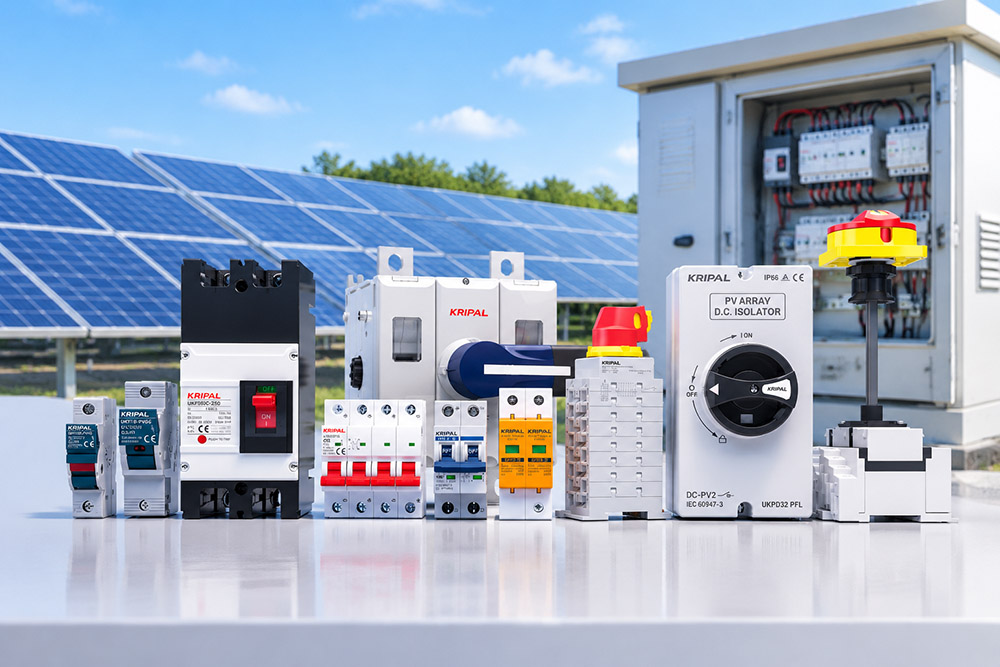
KRIPAL provides DC electrical protection and isolation products for photovoltaic and other DC distribution applications.
Depending on the system design and product ratings, relevant product categories include DC miniature circuit breakers, DC molded case circuit breakers, DC isolator switches and photovoltaic gPV fuse holders.
The rated voltage, current, breaking capacity, pole configuration and terminal specifications should be checked against the requirements of each individual project.
Substitutions That Fail in Service
Several cable substitutions may appear reasonable during installation but can create problems that are not immediately visible.
Conduit Cable on an Open Tray
A cable designed for protected installation may not have the UV and weathering performance required for an exposed rooftop cable route. Before using it outdoors, verify the manufacturer’s declared environmental ratings and applicable cable standard.
Aluminium for Copper at the Same Size
Aluminium and copper have different electrical resistivities. At the same cross-sectional area, aluminium generally has higher electrical resistance and lower current-carrying capability under comparable conditions.
Replacing copper with aluminium therefore requires a new conductor sizing calculation. The terminals and connectors must also be specifically approved for the selected conductor material. Suitable transition or bimetallic connectors may be necessary where dissimilar metals are joined.
A Larger Conductor on a Small Terminal
Increasing conductor size to reduce voltage drop can create a terminal compatibility problem if the connected equipment does not accept the larger conductor.
Cutting away conductor strands to make the cable fit is not an acceptable solution because it reduces the effective conductor cross-section and can compromise the connection.
The correct approach is to verify the terminal capacity before finalizing the cable specification and select compatible equipment or an approved termination arrangement.
Cable construction and conductor selection should always be checked together. For further information, see our related guides on cable and wire differences, types and applications, and calculating voltage drop.
Finalizing Your Cable Specification
A suitable PV string cable must satisfy several requirements at the same time.
The conductor must safely carry the calculated design current after applicable correction factors have been applied. Its cross-sectional area must also keep voltage drop within the project’s design limits.
The cable’s DC voltage rating must be suitable for the maximum system voltage calculated at the lowest expected cell temperature. Its insulation and sheath must meet the environmental requirements of the installation, including temperature, UV exposure and mechanical conditions.
Finally, connectors, terminals and protective devices must be compatible with the selected cable construction and conductor size.
A practical PV cable specification should therefore include:
Field problems do not always originate from an incorrect initial calculation. They can also result from unapproved material substitutions, unsuitable cable construction or poor termination practices.
The actual performance of a cable cannot be established by appearance alone. Its markings, manufacturer’s datasheet, applicable test documentation and installation suitability must be verified before acceptance.
Get Expert Specification Support from KRIPAL
Selecting the right cable is only one part of designing a reliable photovoltaic DC system. The associated protection and isolation devices must also be suitable for the system voltage, operating current and installation conditions.
KRIPAL offers DC protection and isolation solutions for solar PV applications, including DC circuit breakers, DC molded case circuit breakers, DC isolator switches and photovoltaic fuse holders.
For project-related product selection, provide the following information:
Our team can help identify suitable KRIPAL DC protection products based on the supplied project requirements and product specifications.
Frequently Asked Questions
How do I calculate the correct cable size for a solar PV string?
Start with the PV module short-circuit current, number of parallel strings and applicable design factors. Then apply the relevant temperature and installation correction factors to verify current-carrying capacity. Finally, calculate voltage drop using the actual cable route length and conductor resistance.
Why does PV cable selection need to consider cold-weather voltage?
PV module open-circuit voltage generally increases as cell temperature decreases. The maximum string voltage must therefore be calculated using the lowest expected cell temperature to ensure that cables, connectors and connected DC equipment have adequate voltage ratings.
Can a 1,000 V AC cable be used in a 1,000 V DC solar PV system?
Not automatically. AC and DC ratings are established under different conditions. The cable must have a manufacturer’s declared DC voltage rating suitable for the maximum calculated PV system voltage and the applicable cable standard.
What standards are relevant to solar PV DC cables?
IEC 62930 and EN 50618 are important references for photovoltaic cable construction and performance. IEC 62548-1 provides broader PV array design requirements, including DC wiring and electrical protection. The applicable edition and local adoption should be checked for each project.
Why should PV connectors from different manufacturers not be mixed?
Similar-looking connectors may have different contact dimensions, materials, tolerances and sealing characteristics. Unless compatibility has been specifically verified and approved, connectors from the same manufacturer and compatible product series should be used.
Related Resources
Explore Knowledge Center >
Need a matching KRIPAL product?
Share voltage, quantity and destination. An engineer will reply with options and lead time.
