


 Search
Knowledge Center
Using Terminal Temperature to Detect Electrical Connection Problems
Learn how to detect connection issues by monitoring electrical terminal temperatures. A guide on connection resistance, thermal records, and inspections.
 August 09, 2026
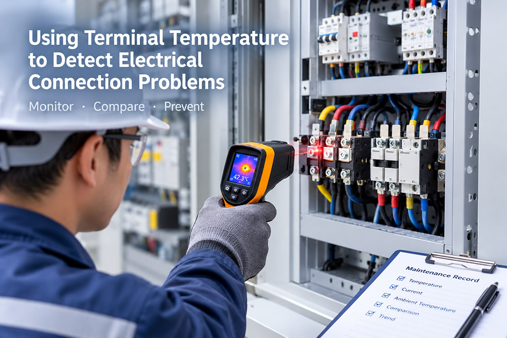
A terminal that is running warmer than expected can provide an early indication of an electrical connection problem. As connection resistance increases, heat generation can increase under load, allowing maintenance teams to identify some developing issues before they lead to equipment failure.
This guide explains why electrical terminals heat up, how to take temperature readings consistently, and how to interpret changes over time. The goal is not to rely on one temperature value, but to use temperature comparisons and historical records as part of a preventive maintenance routine.
Why Electrical Terminals Heat Up
Heat at an electrical terminal is influenced by several factors, with connection resistance and load current being two of the most important.
Connection Resistance
A properly made terminal connection should provide a low-resistance electrical path. Oxidation, corrosion, contamination, conductor damage, or insufficient clamping force can increase the resistance of the connection.
The heat generated by a resistive connection follows the relationship:
P = I²R
This means that as current increases, the effect of connection resistance on heat generation becomes more significant. Clamping conditions can also change over time. Thermal cycling, vibration, and differences in thermal expansion between materials can affect a connection. A terminal that was correctly installed at commissioning may therefore require inspection later in the equipment’s service life.
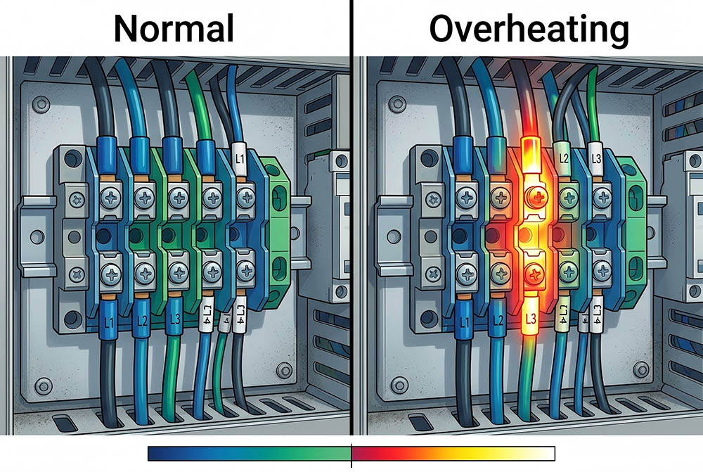
Infrared thermography comparison between normal terminals (left) and an overheating terminal (right) caused by increased connection resistance.
Load and Ambient Temperature
A terminal carrying more current will generally operate at a higher temperature than the same connection under a lighter load. Ambient temperature also affects the measured temperature. For this reason, an absolute temperature value has limited meaning when considered alone. Comparing similar terminals under similar operating conditions can provide more useful information, while current and ambient temperature should also be considered.
Taking a Temperature Reading That Means Something
The value of a temperature measurement depends not only on the instrument but also on how consistently the measurement is taken. A different measurement method, location, load condition, or ambient condition at each visit can make the readings difficult to compare. Consistency is what turns individual measurements into a useful maintenance trend.
Compare Before Measuring
For a three-phase circuit, compare the corresponding terminals across the phases when the operating conditions are reasonably similar. For a DC circuit, the two poles can also be compared where appropriate. A terminal that is noticeably warmer than comparable terminals deserves further investigation, even if its absolute temperature does not appear unusually high.
The second comparison is against the same terminal during a previous inspection. This historical record helps identify whether the connection is stable or its temperature is gradually changing.
A single reading has limited context. A trend is more useful.
Where to Take the Reading
The measurement should focus on the terminal or connection point rather than only the middle of the conductor or the general device body. A localized hot spot at a connection may not be obvious from the temperature of the surrounding device. For infrared measurements, use a consistent measurement location and method at each inspection. Where possible, measurements should be made without changing the normal operating condition of the equipment. If covers or barriers must be removed to access a measurement point, the applicable electrical safety procedure must be followed, and the measurement conditions should be recorded so that future readings remain comparable.
What Different Comparisons Tell You
| Comparison | What it can indicate | What it cannot determine by itself |
| Terminal vs. comparable terminals | Whether one connection is operating differently | Whether the temperature is within the manufacturer’s acceptable limit |
| Terminal vs. its previous reading | Whether the connection condition may be changing | The exact cause of the change |
| Terminal vs. device body | Whether heat appears localized around the connection | Whether the load is responsible |
| Absolute temperature | The measured operating condition | Whether the condition is acceptable without equipment-specific context |
What a Change in Temperature Can Indicate
A change in temperature is often more useful than a single measurement. The rate and pattern of change can help determine what should be investigated next.
Gradual Rise
A gradual increase over several inspections may indicate a change in connection resistance, clamping condition, corrosion, or another operating condition. Before concluding that the connection itself is faulty, check the load current and surrounding conditions. If the current remains similar while one terminal continues to become warmer than comparable terminals, the connection should be inspected according to the equipment manufacturer’s procedure.
Simply tightening a terminal may not correct damaged, oxidized, contaminated, or otherwise degraded contact surfaces. Where inspection confirms a degraded connection, the appropriate re-termination or replacement procedure should be followed. A temperature difference between phases can also result from load imbalance. Checking the current in each phase helps distinguish a load-related temperature difference from a localized connection problem.
Sudden Change
A significant change between two inspections may indicate a recent change in operating conditions or connection condition. Possible factors include:
- A loosened connection
- An improperly re-terminated connection
- A change in load current
- A change in ambient conditions
- A change in the connected equipment
A sharp temperature increase should be investigated rather than ignored until the next routine inspection.
Higher temperatures can accelerate material degradation and may cause an already deteriorating connection to become less stable. The exact cause should therefore be identified before deciding on corrective action.
Building a Temperature Inspection Record
The record is what turns a temperature measurement into a useful maintenance method.
A simple inspection sheet is enough. It does not need to be electronic.
What to Record
At minimum, record:
- Terminal identification
- Terminal temperature
- Load current
- Ambient temperature
- Date and time
- Measurement method
- Previous temperature, where available
- Any corrective action taken
Terminal identification is particularly important. A temperature record is only useful if the same physical connection can be identified during the next inspection.
Terminal Temperature Inspection Checklist
| Item | Example |
| Terminal ID | L1 |
| Terminal temperature | 42°C |
| Phase current | 36 A |
| Ambient temperature | 25°C |
| Previous reading | 40°C |
| Temperature change | +2°C |
| Observation | Slight increase |
| Action | Continue monitoring |
The numbers above are an example of how to structure a record, not universal pass/fail limits. Acceptable operating temperatures and corrective actions should be determined according to the applicable equipment, component, conductor, installation requirements, and manufacturer specifications.
How Often Should Terminals Be Checked?
Inspection frequency should depend on the installation and its operating history. A stable installation may be inspected as part of its normal maintenance program. Equipment operating in high-temperature, humid, corrosive, high-vibration, or heavily loaded environments may require more frequent inspection. If a terminal shows a consistent temperature increase or a significant difference from comparable connections, the inspection interval should be reviewed and the connection investigated according to the applicable maintenance procedure.
What a Rising Temperature Looks Like in Practice
Different temperature patterns can point maintenance teams toward different checks.
| Pattern | What it may suggest | Recommended next step |
| One terminal is warmer than comparable terminals but remains stable | Possible difference in connection condition or operating condition | Check current, installation condition, and manufacturer’s requirements |
| One terminal gradually rises over several inspections | Possible increase in connection resistance or change in clamping condition | Inspect the connection and follow the manufacturer’s procedure |
| All terminals on one phase are warmer | Possible load imbalance or phase-specific operating condition | Check phase currents first |
| All terminals are warmer than the previous visit | Ambient or load conditions may have changed | Compare current and ambient records |
| Terminal and nearby device are both warm | The device itself may be contributing heat | Measure the terminal directly and investigate the heat source |
The key distinction is between a terminal that is simply warm and one whose temperature is changing abnormally relative to comparable terminals or its own history.
Related Component: Thermal Overload Relay
Temperature is also an important consideration when maintaining motor control equipment.
Thermal overload relays protect motors against sustained overload conditions, and their thermal characteristics are influenced by operating conditions and ambient temperature. Checking the relay setting and the surrounding operating conditions during routine maintenance can therefore complement terminal inspections.
KRIPAL offers thermal overload relay options covering 22 A to 630 A across seven setting ranges. For applications where the appropriate component needs to be selected, the terminal type, conductor size, load current, and application conditions should be considered together.
Safety Note
Temperature checks on energized electrical equipment should only be performed by qualified personnel following the applicable electrical safety procedures. Do not remove covers, barriers, or guards or access live terminals solely to obtain a temperature reading. Where an inspection requires access to energized parts, follow the required isolation, PPE, approach-distance, and electrical safety procedures for the installation.
Final Check
Terminal temperature can be a useful maintenance indicator, but it should not be treated as a stand-alone pass/fail measurement.
The most useful approach is to combine:
Temperature + Load Current + Ambient Conditions + Terminal Comparison + Historical Trend
Together, these measurements can help maintenance teams identify abnormal changes earlier and determine when a connection requires further inspection. If you are troubleshooting a terminal temperature issue or selecting a suitable electrical component, send KRIPAL the terminal type, conductor size, load current, and a photo of the installation. The technical team can help evaluate the application and identify a suitable component.
Frequently Asked Questions
There is no single temperature value that can determine whether an electrical connection is faulty. Terminal temperature should be evaluated together with load current, ambient temperature, comparable terminals, equipment requirements, and previous inspection records. A terminal that is significantly warmer than comparable connections or shows a consistent temperature increase may require further investigation.
A hotter terminal may be related to increased connection resistance, changes in clamping conditions, corrosion, contamination, conductor issues, load imbalance, or other operating conditions. Before concluding that the connection is faulty, check the current and ambient conditions and compare the terminal with similar connections under similar operating conditions.
Infrared thermography can help identify abnormal temperature differences and localized hot spots around electrical connections. However, a thermal image alone cannot determine the exact cause of the temperature increase. Further inspection should follow the applicable equipment and manufacturer procedures.
Inspection frequency depends on the installation and its operating history. Stable installations can be inspected as part of their normal maintenance program, while equipment exposed to high temperatures, humidity, corrosive environments, vibration, or heavy loads may require more frequent inspection. A consistent temperature increase may also be a reason to review the inspection interval.
First, compare the terminal temperature with previous readings and with comparable terminals. Then check load current, ambient conditions, and the physical condition of the connection. If the terminal continues to become warmer while operating conditions remain similar, the connection should be inspected according to the equipment manufacturer’s procedure.
Related Resources
Explore Knowledge Center >


Need a matching KRIPAL product?
Share voltage, quantity and destination. An engineer will reply with options and lead time.
