


 Search
Knowledge Center
Arc Flash Boundaries Around DC Equipment: Key Factors for Battery Energy Storage Systems
Guide to calculating DC arc-flash boundaries in BESS applications. Learn key factors, calculation methods, and protection device selection with KRIPAL.
 August 13, 2026
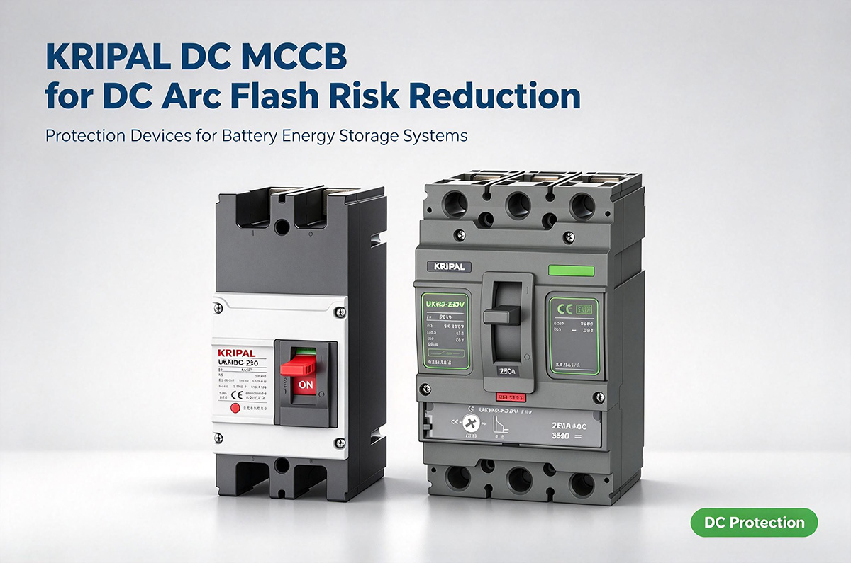
Direct current equipment is widely used in battery energy storage systems (BESS), photovoltaic installations, and industrial power applications. When a fault creates an electrical arc, the resulting thermal energy can present a serious hazard to people working on or near the equipment.
Assessing an arc-flash boundary in a DC system requires attention to the available fault current, arc duration, working distance, and equipment configuration. Protective devices such as DC molded case circuit breakers (DC MCCBs) are part of the protection strategy, but a breaker’s frame rating alone cannot determine the incident energy or boundary. A system-specific assessment is necessary.
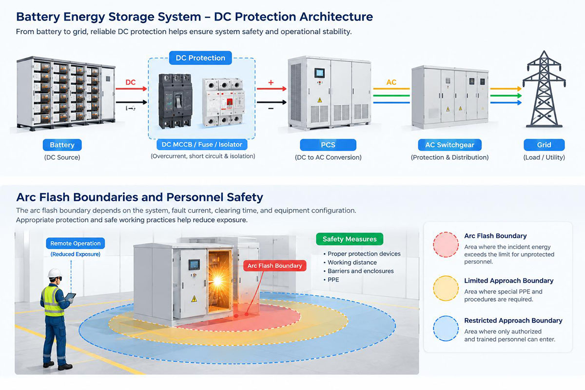
Why DC Arc Flash Hazards Need Careful Assessment
In AC systems, current passes through zero periodically, which can help an arc extinguish under suitable conditions. DC systems do not have the same natural current-zero behavior. A DC arc may therefore persist until circuit conditions and the protection system interrupt the current or the arc can no longer be sustained.
Arc duration is an important factor because, under otherwise similar conditions, a longer-lasting arc generally releases more energy. However, incident energy at a worker’s position is not determined by clearing time alone. Arc voltage and current, system impedance, equipment geometry, working distance, and the calculation method can all affect the result.
Battery Energy Storage Systems: Fault Current Is System-Dependent
Battery energy storage systems can supply substantial fault current from stored energy. The actual current depends on factors such as battery chemistry and configuration, internal resistance, cable and busbar impedance, connections, and the location and type of fault. Current should not be assumed to remain constant throughout a fault.
Nor should battery systems automatically be assumed to have the highest incident energy in every comparison. Arc-flash risk depends on the complete installation and its operating conditions. Engineers should evaluate the relevant fault scenarios rather than rank systems by source type alone.
What Determines a DC Arc-Flash Boundary?
An arc-flash boundary is associated with a defined incident-energy criterion under the selected assessment method. Establishing it requires reliable system data and a method suitable for the DC installation. Important inputs commonly include:
-
✦
Fault Current & Voltage
-
✦
Estimated Arcing Current
-
✦
Device Clearing Time
-
✦
Working Distance Data
-
✦
Operating Scenarios
-
✦
Equipment Geometry
These inputs should be collected and reviewed as part of a documented assessment. A nominal current rating or frame size is not a substitute for the actual time-current characteristics and interrupting capability of the selected device.
Choose a Calculation Method That Applies to DC Systems
Do not assume that an AC arc-flash calculation method can be applied directly to a DC installation. IEEE 1584-2018 provides calculation models for specified three-phase AC systems; it does not provide a general calculation model for DC systems. The engineer responsible for the assessment should select a recognized method that is appropriate to the system voltage, equipment configuration, and available data, and document the method’s assumptions and limitations.
Where the available data or method does not support a defensible numerical result, avoid presenting an estimated boundary as if it were verified. A qualified electrical safety professional should review the study and determine the appropriate controls for the installation.
How DC Protection Devices Affect Risk
Protective-device performance is an important part of DC arc-flash risk management. A device that interrupts a relevant fault more quickly may reduce arc duration, but the actual effect depends on the arcing current and the device’s operating characteristics. Faster settings may also affect selectivity and coordination with upstream devices, so protection coordination and arc-flash assessment should be reviewed together.
When evaluating a DC MCCB for a battery or power-conversion application, verify the specific model’s DC voltage rating, current rating, interrupting capacity, pole configuration and required series or parallel connection arrangements, trip characteristics, and suitability for the system’s grounding and wiring configuration. Use the manufacturer’s technical documentation and the system study rather than relying on frame size alone.
KRIPAL DC MCCBs may be considered as part of a DC protection design when the specific product ratings and characteristics match the application requirements. Product selection should be based on the actual datasheet and engineering review; no single breaker rating is suitable for every BESS installation.
Where DC Arc-Flash Exposure May Occur in BESS
Battery terminals and racks: Battery connections can have high available fault current. Inspection, maintenance, and torque checks should be planned with appropriate isolation, tools, procedures, and exposure controls.
Inverter and combiner equipment: Power-conversion equipment may contain capacitors that remain charged after isolation, while combiner equipment may connect multiple strings. Follow the manufacturer’s discharge times and verify the required safe condition before work.
Cable joints and DC busbars: Connections can require inspection or maintenance and may be exposed to fault energy from connected sources. Correct installation, inspection, and avoiding unnecessary energized work can reduce exposure.
Depending on the circuit design, appropriately rated DC fuses may also form part of the protection strategy. The device type and rating must be selected for the actual system and fault conditions.
Practical Measures to Reduce Arc-Flash Risk
-
✦
Suitable DC Methods
-
✦
Verified Device Ratings
-
✦
Joint Coordination Review
-
✦
Remote Switching Design
-
✦
LOTO & Discharge Plans
-
✦
Barriers & PPE Protocol
-
✦
Updated Work Labels
Remote operation, barriers, and personal protective equipment do not necessarily reduce the incident energy produced inside equipment. They can, when appropriately designed and applied, reduce personnel exposure or consequences. Their effectiveness should not be assumed without considering the specific installation.
Frequently Asked Questions (FAQ)
An arc-flash boundary is the distance from a potential arc source at which the incident energy reaches a defined threshold for assessing burn risk. It should be determined using an appropriate assessment method and the actual system conditions, rather than estimated from equipment size or voltage alone.
Battery energy storage systems can supply substantial fault current, depending on battery characteristics, system configuration, and fault location. A DC arc may continue until the circuit is interrupted or the arc can no longer be sustained, creating a risk of thermal injury and equipment damage.
Key factors include available fault current, protective-device clearing time, working distance, electrode configuration, and the characteristics of the equipment. A qualified electrical professional should assess these factors using a method applicable to the specific DC system.
A properly selected DC molded case circuit breaker (DC MCCB) can help interrupt qualifying overcurrent and short-circuit faults. Its actual contribution to risk reduction depends on its DC voltage and interrupting ratings, trip characteristics, installation, and coordination with other protective devices. A breaker’s frame rating alone does not establish the arc-flash boundary.
No. An arc-flash boundary relates to thermal energy exposure from an arc event, while shock approach boundaries address the risk of electric shock from exposed energized parts. They serve different purposes and should be assessed separately under the applicable electrical safety requirements.
Risk-reduction measures may include selecting suitable protective devices, verifying protective-device settings and clearing times, maintaining equipment, using remote operation where appropriate, installing suitable barriers, and following documented safe-work procedures. The measures should be based on a system-specific risk assessment and applicable regulations.
Conclusion
DC arc-flash boundaries cannot be determined from breaker frame size or source type alone. A reliable assessment considers the available fault current, arc duration, equipment configuration, working distance, and a calculation method appropriate to the DC system.
For battery energy storage and other DC applications, protective devices such as DC MCCBs should be selected using verified product ratings and system-specific engineering data. KRIPAL’s DC protection products can be evaluated as part of that design process when their documented characteristics meet the application requirements.
For product information, contact KRIPAL and provide the system voltage, available fault-current data, protection requirements, and relevant coordination-study information where available. These details help the technical team understand the application; final device selection and arc-flash assessment should be confirmed by qualified personnel.
Technical References
IEEE Std 1584-2018, Guide for Performing Arc-Flash Hazard Calculations. Its calculation models apply to specified three-phase AC systems; they are not a general DC arc-flash calculation method.
Applicable local electrical safety regulations, manufacturer documentation, and a recognized DC arc-flash assessment method suitable for the installation.
Need Engineering Guidance for Your DC Arc Flash Assessment & Protection Devices?
Related Resources
Explore Knowledge Center >

Need a matching KRIPAL product?
Share voltage, quantity and destination. An engineer will reply with options and lead time.
