A contactor that develops an electrical or mechanical fault can prevent a motor from starting, leave a circuit energized after a stop command, or cause unreliable switching. A multimeter can help identify several common problems before they develop into more serious failures.
The basic troubleshooting sequence is straightforward: check the coil, check the main contacts, and check the auxiliary contacts. However, each measurement must be performed with the correct test conditions. This guide explains how to test a contactor with a multimeter, what different readings can indicate, and what a multimeter test cannot confirm.
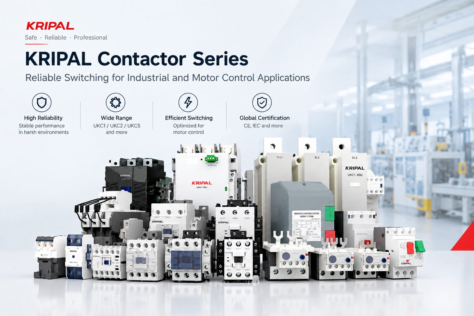
KRIPAL manufactures the UKC1, UKC2, and UKC5 contactor ranges for industrial switching and motor-control applications. The exact coil resistance and contact specifications should always be checked against the datasheet for the specific model.
Safety First: Isolate and Verify the Circuit Is Dead
Before testing a contactor, isolate the circuit from all sources of electrical energy.
A contactor can have separate main and control circuits. Switching off the main circuit breaker does not necessarily remove voltage from the contactor coil. The coil may be supplied by a separate control transformer, PLC output, or other control circuit.
Before connecting a multimeter in resistance or continuity mode:
- Isolate the main power supply.
- Isolate the control circuit and coil supply.
- Apply the required lockout/tagout procedure.
- Verify that the contactor terminals are de-energized using an appropriate voltage tester.
- Confirm that no independent control or auxiliary supply remains connected.
Never use the resistance or continuity function of a multimeter on an energized circuit. Resistance measurements require the circuit under test to be de-energized.
Test 1
Check the Contactor Coil
The coil creates the magnetic field that pulls the contactor mechanism into the energized position. An open or shorted coil can prevent the contactor from operating correctly.
With the control circuit isolated, identify the coil terminals, normally marked A1 and A2.
Set the multimeter to resistance mode and measure directly across A1 and A2.
What the Coil Resistance Reading Means
There is no universal resistance value for a contactor coil. The expected resistance depends on factors such as:
- Coil voltage
- AC or DC coil design
- Contactor model and size
- Coil construction
- Manufacturer-specific design
For this reason, do not use a generic resistance range as the acceptance criterion. Compare the measured value with the manufacturer’s specification for the exact contactor and coil.
An open circuit or an extremely high/infinite resistance reading can indicate a broken coil winding. A reading substantially lower than the specified value may indicate a shorted or damaged winding.
A resistance reading within the expected range does not prove that the coil is fully functional. For example, a coil can have an intermittent or partial fault that is not obvious from a simple resistance measurement.
Continuity Check
A continuity function can provide a quick preliminary check.
With the circuit isolated, connect the meter across A1 and A2. A continuous winding will normally show continuity, while an open winding will show no continuity.
However, continuity alone is not a complete coil test. The measured resistance should still be compared with the manufacturer’s specified value.
Test 2
Check the Main Contacts
The main contacts carry the load current and are subject to electrical and mechanical wear. Common contact problems include welded contacts, pitting, contamination, and excessive contact resistance.
The main contact test should be performed with the contactor de-energized.
Checking for Welded Contacts
A normally open main contact should be open when the contactor is in its normal, de-energized state. With the circuit isolated, place the multimeter across the appropriate line and load terminals of the contact. For a healthy normally open contact, the meter should indicate an open circuit when the contactor is at rest.
If the contactor mechanism can be safely operated manually according to the manufacturer’s instructions, the contact can then be closed and measured again. When the contact closes, the resistance should become very low compared with the open-circuit state.
Another option is to perform a functional test using the contactor’s rated coil voltage. In that case, remove the multimeter from the resistance-measurement circuit before energizing the coil. After the functional test, de-energize and isolate the circuit again before repeating any resistance measurement.
A contact that remains electrically closed after the coil has returned to its de-energized state may indicate welded contacts. A welded contact is a serious fault because the contactor can no longer reliably disconnect the affected circuit. A motor may continue running after a normal stop command until another correctly rated protective or disconnecting device isolates the circuit.
Checking for High Contact Resistance
A standard multimeter can identify an obviously abnormal resistance condition, but it should not be treated as a precision instrument for verifying milliohm-level contact resistance.
When a contact is closed, a healthy contact should normally show a very low resistance reading, often close to the resistance introduced by the test leads and connections.
If the measured resistance is clearly higher than expected, possible causes include:
- Pitted contact surfaces
- Contamination
- Oxidation
- Poor terminal connections
- Mechanical contact problems
High contact resistance can generate heat when current flows through the contact. That heat can accelerate contact degradation and may eventually cause more serious failure.
For applications where precise contact resistance is important, use the manufacturer’s specified test method or a dedicated low-resistance ohmmeter rather than relying on a standard multimeter alone.
Test 3
Check the Auxiliary Contacts
Auxiliary contacts are used for control functions such as status feedback, electrical interlocking, signaling, and PLC inputs.
Their normal state depends on whether the auxiliary contact is normally open (NO) or normally closed (NC).
With the contactor de-energized:
- A NO auxiliary contact should be open.
- A NC auxiliary contact should be closed.
After a properly performed functional operation:
- The NO contact should close.
- The NC contact should open.
The exact terminal identification should always be confirmed from the contactor’s markings or datasheet.
The Electrical Interlock Check
Auxiliary contacts are particularly important in reversing contactor arrangements. In a typical reversing control circuit, an NC auxiliary contact from one contactor is placed in series with the coil circuit of the opposite contactor. This electrical interlock helps prevent both contactors from being energized simultaneously.
For example, when the forward contactor is energized, its NC auxiliary contact in the reverse coil circuit should open and prevent the reverse contactor from receiving its normal control command. A welded or mechanically stuck NC auxiliary contact can compromise this electrical interlock.
However, an electrical interlock should not automatically be treated as a substitute for a specified mechanical interlock. Where the contactor assembly requires mechanical interlocking, the manufacturer’s specified mechanical interlock should also be installed and maintained.
The Status Feedback Check
An auxiliary NO contact may also provide status feedback to a PLC, indicator lamp, or control system. The contact should change state consistently when the contactor operates and return to its normal state after dropout.
If an auxiliary contact remains closed after the contactor has de-energized, or otherwise fails to follow the main contactor mechanism, the control system may receive an incorrect indication of the equipment state.
What a Multimeter Can—and Cannot—Tell You About a Contactor
A multimeter is a useful troubleshooting instrument, but it does not provide a complete assessment of a contactor. The table below shows what a basic multimeter can help identify and what requires additional testing or inspection.
| A Multimeter Can Help Check |
What the Test Can Indicate |
A Multimeter Cannot Reliably Confirm |
| Coil resistance |
An open winding, an obviously abnormal resistance, or a possible shorted coil |
Whether the coil will operate correctly under all operating conditions |
| Coil continuity |
Whether the coil winding has an electrical path |
Coil insulation condition or long-term reliability |
| Main contact state |
Whether a normally open contact is open at rest or remains closed when it should be open, which may indicate welded contacts |
Whether the contact can safely carry its full rated current |
| Closed-contact resistance |
An obviously abnormal resistance or poor electrical connection |
Precise milliohm-level contact resistance when using a standard DMM |
| Auxiliary contacts |
Whether NO and NC auxiliary contacts change state correctly |
Complete mechanical endurance or long-term contact reliability |
| Electrical interlock contacts |
Whether the auxiliary NC contact used for interlocking changes state correctly |
Whether the complete safety or reversing-control system provides adequate protection |
| Basic continuity |
Whether a circuit path is open or closed |
Temperature rise, arc performance, insulation strength, or dielectric withstand |
| Terminal connections |
An obvious open circuit or unusually high resistance connection |
Whether the connection will remain reliable under continuous rated load |
A contactor that passes a basic multimeter test may still require further inspection. For critical applications, contact performance, temperature rise, insulation, mechanical operation, and other characteristics should be evaluated according to the manufacturer’s specifications and applicable test procedures.
What the Readings Mean
Multimeter readings should always be interpreted according to the contactor’s design and manufacturer’s specifications. An infinite or open reading across a coil can indicate an open winding. A resistance substantially outside the specified range can indicate a damaged coil.
For contacts, an open reading across a normally open contact in the de-energized state is normally expected. If that contact remains electrically closed when it should be open, welded or mechanically stuck contacts should be investigated.
When a contact is closed, a standard multimeter should generally indicate very low resistance. However, a basic DMM is not suitable for proving a precise milliohm-level contact resistance value. If a contactor shows abnormal resistance, inconsistent switching, visible contact damage, overheating, unusual noise, or unreliable operation, further inspection or replacement may be necessary.
Recommended Contactor Solutions for Industrial Switching
A contactor is only as reliable as the complete switching and control system around it. Correct coil selection, contact configuration, rated operational conditions, auxiliary contacts, protection, and interlocking all need to match the application.
KRIPAL’s UKC1, UKC2, and UKC5 contactor ranges are designed for industrial switching and motor-control applications. For model-specific coil options, contact configurations, ratings, and technical data, refer to the corresponding product datasheet rather than relying on generic test values. Explore the full contactors and relays range for related switching and control products.
FAQ
What resistance should a contactor coil read?
There is no single resistance value that applies to every contactor coil. The correct value depends on the coil voltage, AC/DC design, contactor model, and coil construction. Always compare the measurement with the manufacturer’s datasheet for the specific coil.
How do I test a contactor without power?
With the main and control circuits fully isolated and verified dead, you can test coil resistance and the normal state of the main and auxiliary contacts with a multimeter. A functional pull-in test requires the correct rated control voltage and should only be performed after the meter has been removed from the resistance-measurement circuit.
Why does my contactor keep the motor running after the stop command?
Welded main contacts are one possible cause. With the circuit isolated, check whether a normally open main contact remains electrically closed after the contactor has returned to its de-energized state. Also investigate the control circuit and any other equipment that could maintain the motor supply.
Can I test a contactor in the panel?
Yes, provided the appropriate safety procedures are followed. Resistance and continuity tests require the relevant circuit to be isolated and verified dead. If a live functional test is necessary, it should be performed only by qualified personnel using appropriate procedures and instruments.
What is a good reading for a main contact?
A closed main contact should normally show very low resistance on a standard multimeter. The exact value depends on the test instrument, test leads, connections, and contactor design. A standard DMM should not be used as definitive proof of milliohm-level contact resistance.
Do UKC1, UKC2, and UKC5 contactors use the same testing procedure?
The basic troubleshooting sequence—checking the coil, main contacts, and auxiliary contacts—can be applied to UKC1, UKC2, and UKC5 contactors. However, the expected coil resistance, contact configuration, and electrical specifications should always be checked against the datasheet for the specific model.
Test It Before It Fails
Testing a contactor with a multimeter is a practical way to identify several common electrical and mechanical problems. The basic sequence is to check the coil, verify the main contacts, and confirm the auxiliary contacts and interlocking functions.
The most important point is to interpret the readings correctly. A continuity beep does not prove that a contactor is suitable for full-load operation, and a resistance value should not be judged against a generic number when the manufacturer’s specification is available.
For reliable troubleshooting, combine multimeter measurements with visual inspection, the manufacturer’s technical data, and appropriate functional tests.
KRIPAL’s UKC1, UKC2, and UKC5 contactor ranges provide solutions for industrial switching and motor-control applications. Contact KRIPAL with your contactor model or application requirements to obtain the relevant technical specifications and product information. Browse the contactor range, related contactors and relays, or contact us for application support.
Request a Quote



 Search
 August 01, 2026