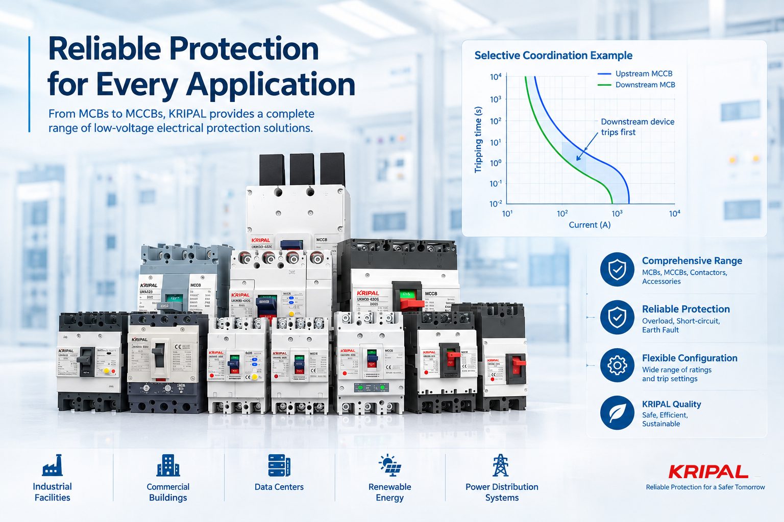
When a fault occurs in an electrical distribution system, the ideal result is simple: the protective device closest to the fault operates first, while upstream devices remain closed. This is the principle of selective coordination, also called selectivity. Without proper coordination, a fault on a small downstream circuit can unnecessarily disconnect a larger part of the installation. Instead of isolating only the faulted circuit, an upstream breaker may also trip, interrupting power to equipment that is still operating normally.
Selective coordination is particularly important in systems where continuity of power matters, including emergency systems, standby power systems, critical operations, industrial distribution, and other installations where an unnecessary outage can have serious consequences.
For manufacturers and system designers, achieving selectivity is not simply a matter of choosing breakers with different current ratings. The actual trip characteristics, available fault current, device combination, and manufacturer coordination data all need to be considered.
KRIPAL’s UKM30 and UKM32 MCCB ranges provide adjustable protection configurations that can be incorporated into properly designed low-voltage distribution systems.
What Is Selective Coordination?
Selective coordination is the ability of a series of protective devices to operate in a defined sequence so that the device nearest to the fault clears the fault while upstream protection remains energized, within the limits established for the system.
Consider a typical distribution chain:
Transformer
Main MCCB
Sub-main MCCB
Branch MCB
Load
If a short circuit occurs on the branch circuit, a selectively coordinated system is designed so that the branch protective device clears the fault without unnecessarily opening the sub-main or main breaker. The result is more than simply “the right breaker trips.” Selectivity reduces the amount of equipment disconnected during a fault and helps maintain power to unaffected loads.
The opposite condition is non-selective operation. Two protective devices may operate together, or an upstream device may operate before the downstream device. In that situation, the faulted circuit is isolated, but healthy parts of the distribution system may also lose power.
How Time-Current Curves Affect Coordination
One of the main tools used to evaluate selective coordination is the time-current characteristic (TCC) curve. A TCC shows the operating time of a protective device at different current levels. The horizontal axis normally represents current, while the vertical axis represents operating time, with both axes typically using logarithmic scales.
For two devices in series, the downstream device should normally have an operating characteristic that allows it to clear the relevant fault before the upstream device operates. The required separation depends on the actual device characteristics and the fault-current range being considered.
However, TCCs should not be treated as the only evidence of complete selectivity. In particular, at high fault-current levels, instantaneous or magnetic protection can become critical. The operating characteristics of two devices may approach or overlap in this region, making coordination more difficult to establish from curves alone.
For this reason, a proper coordination assessment may require manufacturer selectivity tables, tested combinations, engineering software, or other manufacturer data, depending on the equipment and applicable requirements.
Why a 2:1 Current Ratio Is Not Enough
A common rule of thumb is to use a higher-rated upstream breaker, sometimes expressed as a 2:1 ratio between upstream and downstream device ratings. For example, a 63 A upstream device and a 32 A downstream device are approximately 2:1 in rated current.
However, a 2:1 ratio should not be treated as a universal rule for proving selective coordination.
Two breakers with a large difference in ampere ratings can still have overlapping instantaneous characteristics. Conversely, certain combinations with smaller rating differences may achieve selectivity when their trip characteristics and manufacturer data support it.
The correct approach is to verify the specific protective-device combination rather than relying on current rating alone.
Factors that can affect selectivity include:
- Long-time pickup and trip characteristics
- Short-time pickup and delay settings
- Instantaneous or magnetic trip settings
- Available short-circuit current
- Breaker type and trip unit
- The specific upstream and downstream device combination
- Manufacturer coordination or selectivity data
This distinction is important when designing MCCB and MCB combinations for commercial and industrial distribution systems.
Why Selective Coordination Matters for Critical Systems
NEC (United States)
Selective coordination becomes especially important when an unnecessary breaker operation could disable systems that are required during an emergency.
In the United States, the National Electrical Code (NEC) includes selective-coordination requirements for specific systems. For example, NEC Article 700 addresses emergency systems, Article 701 addresses legally required standby systems, and Article 708 addresses critical operations power systems. The specific requirements should always be checked against the edition of the NEC adopted by the authority having jurisdiction.
The engineering reason is straightforward: a fault in one branch circuit should not unnecessarily remove power from other circuits that are still required to operate.
BS 7671 (UK)
In the UK, BS 7671 addresses selectivity under Regulation 536.4. The design and verification of protective-device coordination should take account of the characteristics of the devices and appropriate manufacturer information.
The requirements are not identical between NEC and BS 7671, so designers should apply the standard and edition relevant to the installation rather than assuming that one jurisdiction’s approach can simply be transferred to another.
How to Verify Selective Coordination
A reliable coordination process starts with the complete protection chain rather than with a single breaker.
1
Step 1: Identify the Protection Chain
List the protective devices between the load and the source:
Branch protection
Sub-main protection
Main protection
Transformer/source protection
Consider every relevant protective device in series. A coordination study that overlooks one device can produce an incomplete result.
2
Step 2: Determine the Available Fault Current
Establish the prospective short-circuit current at the relevant points in the installation.
Available fault current depends on factors including the transformer characteristics, source impedance, conductor impedance, and distribution arrangement. The value can vary significantly between the supply point and downstream circuits.
Selectivity must be evaluated over the fault-current range that the installation can experience.
3
Step 3: Review Device Characteristics and Settings
Compare the actual protective devices rather than looking only at their rated currents.
For adjustable MCCBs, review the applicable long-time, short-time, and instantaneous protection settings. The objective is to create an appropriate operating sequence between downstream and upstream protection without compromising the required protection of the conductors and equipment.
4
Step 4: Compare TCCs and Manufacturer Data
Use the manufacturer’s time-current curves and coordination information to assess the device combination.
Where the curves overlap or the instantaneous region becomes significant, manufacturer selectivity tables or tested combinations may be necessary to establish whether the devices remain selective at the required fault-current level.
This is why coordination should always be checked using the actual models and trip units being installed.
5
Step 5: Document the Verification
A coordination assessment should be reproducible.
Record the protective-device types, ratings, trip settings, available fault currents, relevant curves, manufacturer data, and the resulting coordination limits.
For systems subject to specific code requirements, the documentation should also satisfy the applicable project and inspection requirements.
Common Selective Coordination Mistakes
Relying Only on Breaker Ratings
A higher-rated upstream breaker does not automatically guarantee selectivity. Ampere ratings are only one part of the protection characteristics.
Ignoring Instantaneous Protection
At high short-circuit currents, instantaneous or magnetic operation can determine whether two devices remain selective. Adjustable trip settings and manufacturer coordination data therefore become particularly important.
Assuming TCC Curves Prove Everything
TCC comparison is fundamental, but it may not be sufficient in every operating region. Manufacturer coordination tables and tested combinations can provide additional verification where curve overlap occurs.
Treating Coordination as a One-Time Decision
Changing a breaker, trip unit, transformer, cable arrangement, or protection setting can change the coordination result. The protection system should therefore be reassessed when significant changes are made.
MCCBs and Selective Coordination
MCCBs are commonly used as main and feeder protection in low-voltage distribution systems because some models provide adjustable trip characteristics and higher interrupting capabilities than typical branch MCBs.
For a coordinated MCCB/MCB system, the upstream MCCB may be configured with appropriate long-time, short-time, and instantaneous settings to provide separation from downstream protection, where supported by the specific device and permitted by the design.
KRIPAL UKM30 and UKM32 MCCBs are designed for low-voltage distribution applications where flexible protection configuration is required. Their adjustable protection characteristics can help engineers develop suitable protection schemes, but actual selective coordination should always be verified for the specific device combination, settings, and available fault current.
For projects requiring documented coordination, engineers should use the relevant KRIPAL technical data and coordination information for the selected MCCB configuration. Related circuit breakers can also be reviewed as part of the complete protection chain.
FAQ
What is selective coordination in electrical distribution?
Selective coordination means that, when a fault occurs, the protective device closest to the fault operates while upstream devices remain closed within the specified coordination range.
What is the difference between coordination and selectivity?
Coordination is the process of selecting and setting protective devices so that they operate together correctly. Selectivity is the resulting ability to isolate the faulted section while keeping unaffected parts of the system energized.
Can two circuit breakers with different ratings be selectively coordinated?
Yes, but different current ratings alone do not prove selectivity. The actual trip characteristics, fault current, device combination, and manufacturer coordination data must be considered.
How do you verify selective coordination?
A typical verification involves determining the protection chain and available fault current, reviewing device settings and TCC curves, checking manufacturer selectivity data, and documenting the results.
Do MCCBs coordinate with MCBs?
They can, provided the specific MCCB and MCB combination has suitable operating characteristics and is verified for the available fault-current range. Manufacturer coordination data should be consulted where applicable.
Why can an upstream breaker trip before a downstream breaker?
This can occur when the devices are not selectively coordinated for the fault current involved. Similar instantaneous trip characteristics, inappropriate settings, or an unsuitable device combination can cause upstream operation.
The Protection Chain Is Only as Strong as Its Coordination
Selective coordination is a fundamental part of reliable electrical distribution. It helps limit unnecessary outages by ensuring that faults are isolated as close to their source as practical, while upstream protection remains available for unaffected circuits.
Achieving it requires more than applying a fixed current ratio. Engineers should consider the complete protection chain, available fault current, time-current characteristics, trip settings, and manufacturer coordination data.
KRIPAL’s UKM30 and UKM32 MCCBs provide adjustable protection configurations for low-voltage distribution applications where coordination and protection settings need to be carefully engineered.
For a project-specific solution, consult the applicable KRIPAL technical documentation and verify the complete protection scheme against the actual system conditions and relevant electrical standards. Contact the KRIPAL engineering team for application support.
Request a Quote



 Search
 August 03, 2026