Search
News
What Is a Knife Switch and What Has It Become in Modern Electrical Systems?
Why are knife switches obsolete? Learn about modern enclosed switch-disconnectors, AC/DC utilization categories (AC-23, DC-PV2), and key selection criteria.
![]() May 23, 2026
May 23, 2026
The knife switch stands as one of the earliest and most fundamental mechanical switching devices in electrical history. Operating via a straightforward manual metal blade that bridges or separates a circuit through direct contact with a fixed terminal, it served as the backbone of early electrical distribution panels.
However, as modern industrial power systems scaled up in voltage, short-circuit capacities, and safety expectations, the classic open-frame knife switch became an obsolete legacy device. Today, it has completely evolved into a safer, fully enclosed, and standards-compliant solution: the industrial switch-disconnector (or load-break disconnect switch).
This technical guide explores the safety and engineering limitations that drove the knife switch into legacy status, details the distinct operational categories for both AC and DC systems, and explains the core parameters engineers use to specify isolation switchgear today.
Key Takeaways
- Legacy Status: Knife switches are considered obsolete in industrial power systems due to exposed live parts and lack of arc containment.
- Modern Replacement: Switch-disconnectors provide enclosed, touch-safe isolation with controlled load-breaking capability.
- Standards-Based Design: Modern devices are classified under IEC 60947-3 utilization categories (AC and DC), rather than simple current ratings.
- Improved Safety Mechanisms: Spring-assisted quick-make/quick-break systems ensure consistent contact separation independent of operator behavior.
- Application Scope: Widely used in AC distribution systems, PV plants, battery energy storage systems (BESS), and DC infrastructure.
Why Knife Switches Are No Longer Used in Modern Power Systems
Although historically important, the knife switch presents several structural and safety limitations that prevent its use in modern electrical engineering:
Exposed Live Conductors
The open-frame design leaves energized metal parts exposed, creating a high risk of accidental contact and electric shock.
Lack of Arc Containment
Knife switches do not include arc chutes or enclosed extinguishing chambers. When breaking load current, arcs form in free air and may cause severe contact erosion or arc flash hazards.
Operator-Dependent Switching Speed
The separation speed of the contacts depends entirely on manual operation. Slow or inconsistent operation increases arc duration and thermal stress on the contacts.
No Environmental Protection
Without enclosure, knife switches cannot meet modern IP protection requirements. Dust, humidity, and corrosion significantly degrade long-term performance.
Because of these limitations, modern electrical codes (IEC-based standards and regional electrical regulations) restrict knife switches to educational demonstrations or legacy low-risk environments.
What Is a Switch-Disconnector?
A switch-disconnector (also referred to as a load-break isolator) is a mechanical switching device designed to:
- Safely carry current under normal operating conditions
- Switch electrical loads within defined utilization categories
- Provide a visible and reliable isolation gap for maintenance safety
Under IEC 60947-3, switching devices are generally categorized as:
- Switch: Can operate under load but does not guarantee isolation clearance
- Disconnector: Provides isolation but must only be operated under no-load conditions
- Switch-Disconnector: Combines both functions—load switching and safe isolation
Unlike a pure disconnector, a switch-disconnector is designed to interrupt load current within defined limits while still ensuring a physically verifiable isolation gap for maintenance safety.
It typically includes:
- Insulating flame-retardant housing
- Quick-make / quick-break spring mechanism
- Arc-resistant contact system
- Lockout/tagout (LOTO) compatibility.
AC Utilization Categories (IEC 60947-3)
In AC systems, current naturally crosses zero twice per cycle, making arc extinction easier compared to DC systems. However, selecting a switch based only on rated current (Ie) is insufficient.
IEC 60947-3 defines utilization categories based on load type:
AC-21 (Resistive Loads)
Suitable for purely resistive loads such as heating systems and simple distribution circuits.
AC-22 (Mixed Loads)
Designed for mixed resistive and inductive loads, including lighting systems and moderate switching duty.
AC-23 (Motor and Highly Inductive Loads)
Used for motor loads with high inrush current (typically 6–8× rated current) and frequent switching operations.
The “A” and “B” suffixes indicate different test duty conditions defined by IEC standards, primarily related to operational frequency during standardized testing rather than a strict classification of device durability.
DC Utilization Categories: PV and Energy Storage Systems
Direct current systems present significantly higher switching challenges because DC current does not naturally pass through a zero-crossing point during normal operation. As a result, arc interruption requires additional design considerations compared to AC systems.
IEC 60947-3 defines DC utilization categories as application-specific test duty classifications based on load type, switching conditions, and system behavior under defined operating profiles.
| Utilization Category | Typical Applications | Electrical Characteristics | Switching Capability | Key Considerations |
| DC-21B | General industrial DC resistive loads, maintenance isolation switching | Low inductance, stable DC load conditions | Suitable for infrequent switching under normal load conditions | Not intended for photovoltaic or high-energy DC bus applications; limited tolerance to transient overvoltage and inductive effects |
| DC-PV1 | Photovoltaic string circuits in residential and small commercial PV systems | Unidirectional DC with relatively stable operating profile under standard conditions | Suitable for switching under defined PV test conditions | Limited suitability for systems with high parallel string configurations, reverse current events, or inverter-driven dynamic fluctuations |
| DC-PV2 | Utility-scale PV systems, commercial solar farms, and battery energy storage systems (BESS / PCS DC side) | DC systems with higher energy levels and dynamic operating conditions, including potential bidirectional current influence | Designed for more demanding PV test duty conditions with higher switching stress levels | Requires appropriate system coordination in applications with high fault current levels or severe transient conditions |
Engineering Note
In modern 1000V to 1500V DC power architectures, DC-PV2 utilization category devices are commonly selected for photovoltaic and energy storage applications where higher switching stress and more complex system behavior are expected.
The selection of switch-disconnectors should be based on system-level design considerations, including string configuration, inverter characteristics, and expected transient conditions, rather than voltage rating alone.
Structural Innovations in Modern Switch-Disconnectors
Modern enclosed switch-disconnectors improve safety and reliability through several key engineering features:
Spring-Loaded Quick-Make / Quick-Break Mechanisms
To safely interrupt high-voltage AC and stubborn, non-zero-crossing DC-PV2 inductive currents under load, modern switches utilize internal spring-driven energy storage.
When the operator rotates the handle, the internal springs store kinetic energy and snap the contacts apart or together at an ultra-high, uniform speed. This operator-independent action instantly quenches the electrical arc, preventing contact erosion and welding.
Enclosed Visible Isolation Windows
While old knife switches offered visual reassurance through fully exposed blades, modern enclosed designs maintain this safety benefit via a clear, integrated inspection window. Operators can visually verify the physical separation of the internal contacts through a touch-safe, sealed barrier before commencing downtime maintenance.
Modular Multi-Pole Configurations
Modern power architectures require flexible line configurations. Advanced switch-disconnectors are available in 2P to 6P form factors to enable versatile layouts across:
- Three-phase AC distribution grids.
- Dedicated neutral line isolation requirements.
- Multi-string high-voltage DC solar architectures and parallel battery circuits.
Technical Comparison: Knife Switch vs. Modern Switch-Disconnector
| Feature | Legacy Knife Switch | Modern Switch-Disconnector |
| Structure | Exposed metal blade, open frame | Fully enclosed insulating housing |
| Safety Level | Low (Severe risk of shock & open arc flash) | High (Touch-safe, IP-compliant design) |
| Arc Control | None (Relies on air gap manual pulling) | Integrated arc chutes + spring-assisted snap action |
| Load Switching | Not suitable (Highly dangerous under load) | Fully supported up to nominal operational current (Ie) |
| Status Visibility | Fully exposed (Unsafe operating environment) | Secure verification via an integrated inspection window |
| Maintenance Safety | Limited (No verification or manual locks) | Purpose-engineered for Lockout/Tagout (LOTO) padlocks |
| Industrial Status | Obsolete / Legacy training units only | Universal global industry standard |
Core Application Areas
Modern enclosed switch-disconnectors operate as mandatory, un-tripped safety main switches across several critical AC and DC power sectors:
- Industrial Distribution Panels (AC Main Isolation): Serves as the main feeder disconnect for power boxes, allowing technicians to fully de-energize control cabinets before opening enclosure doors.
- Motor Control & Machinery Maintenance (LOTO Systems): Positioned near heavy machinery and conveyor lines, allowing field crews to lock handles in the “OFF” position using personal padlocks to prevent accidental restarts during servicing.
- Photovoltaic Plants & Battery Storage Systems (DC Bus Isolation): Functions as critical Manual Disconnect Switches (MSD) in solar arrays and battery compartments (PCS side). They safely cut high-voltage DC loops (up to 1500VDC) under heavy load, preventing hazardous reverse currents and localized thermal runaways.
- EV Charging Infrastructure & Emerging DC Grids: Widely integrated within EV fast-charging stations, rail transit traction grids, data center HVDC distribution, and heavy electrochemical systems (electroplating/electrolysis) to facilitate modular circuit isolation.
Sourcing and Specification Considerations
When evaluating and specifying an industrial switch-disconnector for global engineering projects, critical parameters must be cross-examined to ensure systemic compliance:
- Rated Operational Voltage (Ue): Must match or exceed the maximum systemic architecture requirements (e.g., up to 690V AC or 1500V DC).
- Thermal Current Rating (Ith): The maximum continuous current the switch gear can carry in free air without exceeding safe thermal thresholds.
- Utilization Category: Must align with the specific load dynamics (e.g., inductive motor switching under AC-23A or severe bidirectional solar dynamics under DC-PV2).
- Short-Circuit Making Capacity (Icm): the ability of the switch-disconnector to safely close under short-circuit conditions without mechanical damage, under defined IEC test conditions.
- Mechanical Endurance & Operating Cycles: Evaluation of durability metrics under frequent on-load switching conditions.
- Enclosure Type and IP Rating: Shielding standards required against dust, moisture, and corrosive pollutants for outdoor or rugged industrial usage.
- Compliance Frameworks: Ensuring verified compliance with international standards, primarily IEC 60947-3, backed by third-party approvals such as TUV, CE, CB.
Industrial Switch-Disconnector Solutions
To meet these precise technical metrics, modern low-voltage component manufacturers provide standardized, high-performance product series tailored for seamless panel integration:
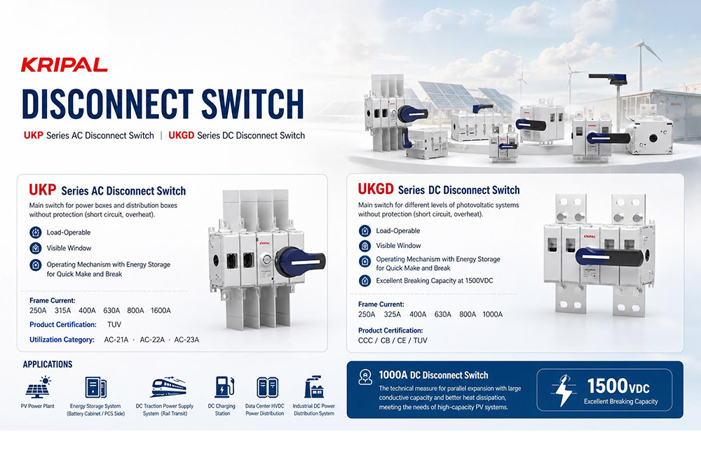
- AC Distribution Switch-Disconnectors (e.g., UKP Series): Scaling from 250A up to 1600A across AC-21A, AC-22A, and AC-23A utilization categories to fit heavy power distribution enclosures, main feeder boards, and power box layouts.
- High-Voltage DC & PV Isolators (e.g., UKGD Series): Supporting high-capacity frame sizes from 250A to 1000A with specialized parallel capacity layouts, guaranteeing robust thermal dissipation and excellent load-break capacity at thresholds reaching 1500VDC.
These modern portfolios ensure complete alignment with international grid codes, offering global EPC contractors and system integrators uncompromising reliability and safety for modern power grids worldwide.
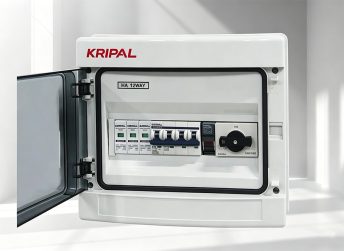
DC-PV2 switch-disconnector for 1500V solar and BESS application
Explore Industrial Switch-Disconnector Technical Specifications
Conclusion
The legacy knife switch proved that physical circuit interruption is the bedrock of electrical safety. However, as modern networks transition toward dense industrial automation and high-voltage 1500VDC solar/storage architectures, open-frame devices are no longer just obsolete—they are a severe operational liability.
For international EPC contractors and panel builders, compliance with IEC 60947-3 is the non-negotiable benchmark for global infrastructure. Modern fully enclosed switch-disconnectors successfully bridge the gap between reliable load-breaking and absolute touch-safe isolation.
By matching exact utilization profiles—such as AC-23A for heavy inductive motors or DC-PV2 for fluctuating solar grids—engineers can definitively eliminate the risk of arc-flash accidents, contact welding, and unplanned system downtime.
FAQs
Q What is the definitive operational difference between a switch-disconnector and a circuit breaker?
They serve completely different roles within a panel. A switch-disconnector is a manual control and isolation device rated to safely break normal operational currents (up to its rated current Ie) and guarantee a safe dielectric gap; it has no automatic fault-sensing capability.
A circuit breaker is an automatic protective device specifically engineered to detect, withstand, and trip under massive, unpredictable short-circuit faults (measured by Icu or Ics) to safeguard upstream transformers and downstream cabling.
Q Why is ultra-fast contact separation vital for 1500VDC operations compared to AC systems?
Alternating Current (AC) naturally passes through a zero-crossing point twice per cycle, which drops the voltage and inherently extinguishes the arcing plasma. Direct Current (DC) has no natural zero-crossings; its continuous power maintains highly stubborn, stable plasma arcs.
When opening high-voltage DC arrays under load, slow contact separation causes intense localized heat that welds contacts or triggers fires. Modern DC disconnectors rely on internal spring-driven energy storage to snap contacts open within milliseconds, forcing the arc instantly into specialized arc chutes.
Q Why do field operators prioritize physical inspection windows over electronic indicators?
In high-stress industrial environments, a massive voltage surge can cause contact material to momentarily melt and weld the internal contacts together. When this happens, forcing the external handle to “OFF” might snap the internal mechanical linkage without actually breaking the electrical circuit.
Electronic flags or handle positions can show a false “OFF” safety status. A heavy-duty, sealed visible inspection window allows maintenance crews to directly verify actual physical contact separation with their own eyes before executing Lockout/Tagout (LOTO) protocols.
Q What does the “A” vs “B” suffix mean in categories like AC-23A vs AC-23B?
The alphabetical suffixes indicate the mechanical and electrical durability tested under standard rating conditions:
- Suffix “A” (Frequent Operation): Certified to withstand highly repetitive on-load switching cycles. This is the mandatory choice for primary main switches in active manufacturing control panels or heavy machine isolators.
- Suffix “B” (Infrequent Operation): Rated for systems rarely toggled under load. It is designed to safely remain closed for months or years at a time, making it ideal for seasonal solar array maintenance or plant utility disconnects.
Q Can a modern switch-disconnector directly retrofit an old knife switch setup?
Yes, but mechanical fit is only half the equation. Beyond aligning physical mounting footprints or utilizing modular shaft extensions, engineers must verify that the enclosure’s continuous thermal current (Ith), rated operational voltage (Ue), and peak short-circuit making capacity (Icm) meet or exceed the original system specifications.
Most importantly, the unit’s utilization category must be cross-checked against the inductive or resistive characteristics (L/R time constants) of the actual application environment.
Related Resources
Explore News >
How can we assist you?
Tell us a bit more so we can route your request to the right expert.