Application Scenarios Matching Components to Motor Requirements
Correct selection depends heavily on the motor power rating, operating environment, and control methodology.
Standard Applications for Low Power and Frequency
Typical Use Cases This category includes fans, pumps, conveyors, and standalone machines with motor power ≤ 15 kW. These typically use manual push-button control and see fewer than 10 starts per day.
Selection Recommendations
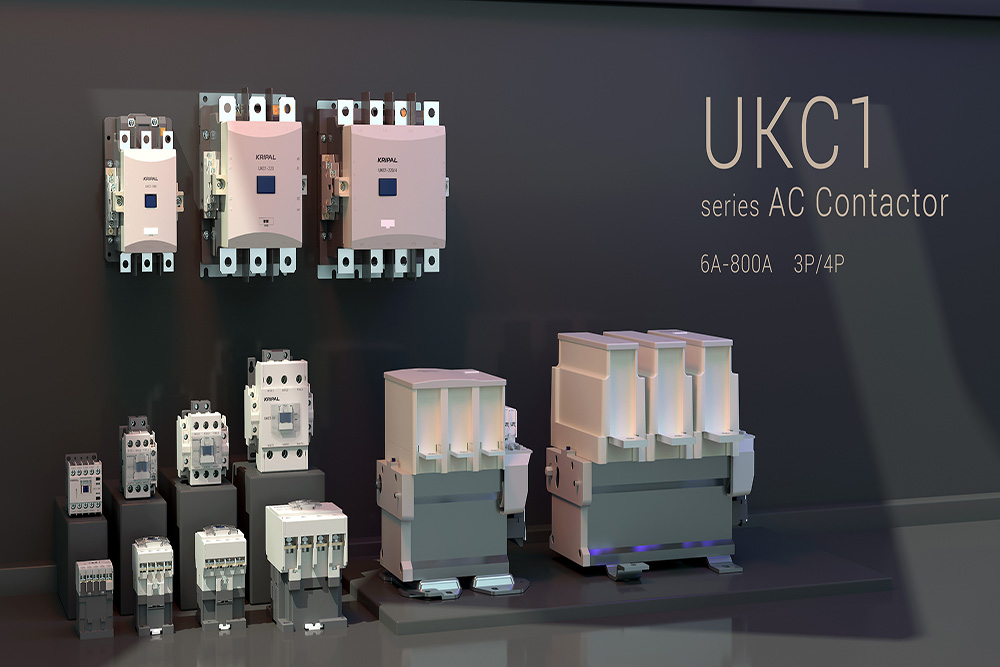
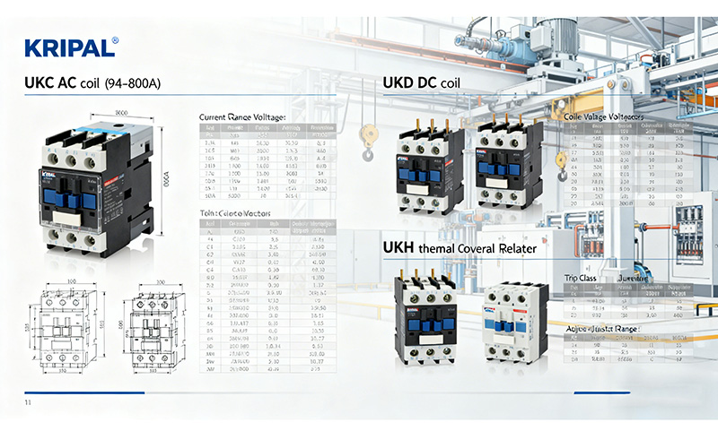
- Contactor: Use a Standard AC coil type(KRIPAL UKC Series). Size it at 1 to 1.3 times the motor rated current. Ensure Utilization Category AC-3.
- Thermal Relay: Choose a model where the adjustment range covers the motor’s rated current (e.g., KRIPAL UKH series).
Automation and High Frequency Applications
Typical Use Cases This covers automated production lines, precision machining, and compressors with motor power ≥ 15 kW. These are often PLC-controlled and may see over 50 starts per day.
Selection Recommendations
- Contactor: Use a DC coil type (KRIPAL UKD Series) for silent operation and anti-interference.
- Sizing: 1.3 to 1.5 times the motor rated current to handle thermal stress.
- Thermal Relay: Select high-precision types that offer fault signal feedback to the PLC.
Operating Logic of Star Delta Starting
For large motors, Direct-On-Line (DOL) starting produces inrush currents 5 to 7 times the rated current. This causes grid voltage dips and mechanical shock. Star-Delta starting reduces this starting current to approximately one-third.
Operating Stages
- Starting (Star Connection): The Main contactor and Star contactor energize. The motor windings receive only ~58% (1/√3) of the line voltage, significantly lowering torque and current.
- Running (Delta Connection): After a set time, the Star contactor opens and the Delta contactor closes. The windings now receive full line voltage, and the motor runs at rated power.
Important Limitation
Star-Delta is only suitable for motors designed for Delta connection at the rated voltage and for applications with light-load starting conditions.
Selection Guide for Star Delta Contactors and Relays
A Star-Delta circuit requires three distinct contactors: Main, Star, and Delta. Because the current flows differently through each branch, they must be sized individually to balance cost and reliability.
Contactor Selection Rules
- Main Contactor : Carries line current during both start and run phases. Rating: 1.1 to 1.3 × Motor Rated Current (In).
- Delta Contactor: Carries phase current (approx. 58% of line current) during the run phase. Rating: 0.6 to 0.8 × Motor Rated Current(In).
- Star Contactor: Carries reduced current only during the brief startup window. Rating: 0.5 to 0.6 × Motor Rated Current (In).
Example Calculation
For a 15 kW motor with a rated current of 30A:
- Main Contactor: 32A (Based on 30A*1)
- Delta Contactor: 20A (Based on 30A *67)
- Star Contactor: 16A (Based on 30A*53)
Thermal Overload Relay Selection
- Placement: Ideally installed in the main circuit (before the split) to provide complete protection.
- Sizing: Select based on the full motor rated line current.
- Setting: Independent of the Star-Delta configuration, the adjustment range must cover the motor In.
- Start Time: For starts lasting longer than 10 seconds, choose saturation CTs or adjustable delay models to prevent nuisance tripping.
Common FAQs and Selection Pitfalls
Q1: Can all three star-delta contactors be the same size?
No. This leads either to unnecessary cost or premature contact failure. Proper current grading is essential.
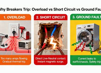
Q2: Can a thermal overload relay replace short-circuit protection?
No. Thermal relays protect against overload only. Short-circuit protection must be provided by circuit breakers.
Q3: Why should thermal relays not be installed at winding ends?
Incorrect installation compromises phase-loss protection and causes inaccurate current sensing.
Q4: How do DC coil contactors integrate with PLCs in star-delta circuits?
DC24V coils (e.g. KRIPAL UKD1 series) connect directly to PLC outputs. Add flyback diodes to protect output modules.
Summary and Product Recommendations
Selecting the correct AC contactor and thermal overload relay is a strategic decision that ensures system reliability and lowers long-term maintenance costs. In modern automation environments, prioritizing DC coil contactors is essential for seamless PLC integration and noise-free operation.
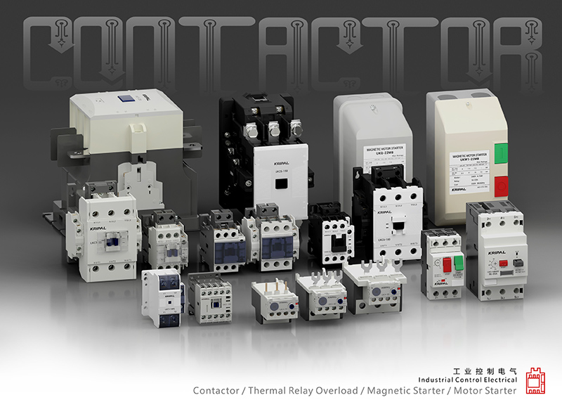
KRIPAL offers a comprehensive portfolio tailored to these distinct needs. The UKC Series provides robust AC coil contactors (9A–800A) ideal for general industrial use, while the UKD Series features silent DC coils optimized for automation. Pair these with our UKH Series thermal overload relays for precision motor protection. If your application involves heavy loads or special duty cycles, Contact KRIPAL Technical Support for precise parameter matching and catalog downloads.


 Search