Search
News
What Is the Difference Between Normally Open and Normally Closed Switches?
Discover the key differences in operation and application between switches as we explore normally open vs normally closed.
![]() January 12, 2026
January 12, 2026
In electrical control systems, “normally open” and “normally closed” describe the default state of switches, relays, or contactors when no external control signal is applied. Understanding these terms and their differences is fundamental to designing and maintaining electrical circuits effectively. This article will explain the definitions, working principles, key differences, and application scenarios of normally open and normally closed switches, helping you make more informed choices in various electrical systems.
Key Takeaways
- Normally Open (NO): In the default state, the contacts are open (circuit is disconnected). When a control signal is received, the contacts close, and the circuit is connected.
- Normally Closed (NC): In the default state, the contacts are closed (circuit is connected). When a control signal is received, the contacts open, and the circuit is disconnected.
- Working Principle: Normally open contacts need an external signal to close, whereas normally closed contacts are closed by default and open when the signal is received.
- Typical Applications: Normally open contacts are used for start buttons and similar operations, while normally closed contacts are used for stop buttons, emergency stop switches, and safety applications.
- Selection Advice: Understanding the working principles of normally open and normally closed switches helps in selecting the right type for your system, ensuring the stability and safety of your electrical circuits.
What Are Normally Open and Normally Closed Switches?
In electrical control systems, normally open and normally closed describe the default state of switches, relays, or contactors when no control signal or external force is applied. Understanding these terms and their differences is key to designing and maintaining electrical circuits efficiently.
- Normally Open (NO)means that the contacts are open in the default state (circuit is disconnected) and close when a control signal is received (circuit is connected).
- Normally Closed (NC)means that the contacts are closed in the default state (circuit is connected) and open when a control signal is received (circuit is disconnected).
These two concepts describe the state of the contacts without external influence and how they change when control signals are applied.
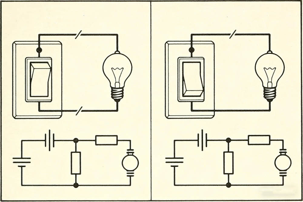
How Normally Open and Normally Closed Switches Work
When there is no power or control signal:
- Normally open contactsremain open by default, preventing current from flowing. The circuit only closes when a control signal is applied, allowing the current to flow.
- Normally closed contactsremain closed by default, allowing current to flow. When a control signal is applied, the contacts open, interrupting the current flow.
This can be compared to doors: a normally open contact works like a door that stays closed by default and needs to be “opened” to allow passage. A normally closed contact behaves like a door that is open by default and only blocks passage when it is “closed” by a signal. This switching mechanism is common in electrical controls such as buttons, sensors, and relays.
Key Differences Between Normally Open and Normally Closed Switches
The table below compares the main differences between normally open (NO) and normally closed (NC) switches in terms of their default state, controlled state, and typical applications:
| Comparison | Normally Open (NO) | Normally Closed (NC) |
| Default State (No Signal / Power Off) | Open, circuit is disconnected | Closed, circuit is connected |
| Controlled State | Closed, circuit is connected | Open, circuit is disconnected |
| Control Logic | Commonly used for starting, initiating, or connecting operations | Commonly used for stopping, emergency stop, or safety interruption |
| Typical Use Example | Motor start button circuit | Emergency stop switch, safety interlock |
| Circuit Behavior Description | Circuit remains open when not activated | Circuit remains closed when not activated |
The default state in the table refers to the condition of the contacts when no signal is applied or when the system is not powered.
Application Examples
To better understand how these switches are used in electrical systems, here are some common scenarios where normally open and normally closed contacts are applied:
- Normally Open Contacts (NO)
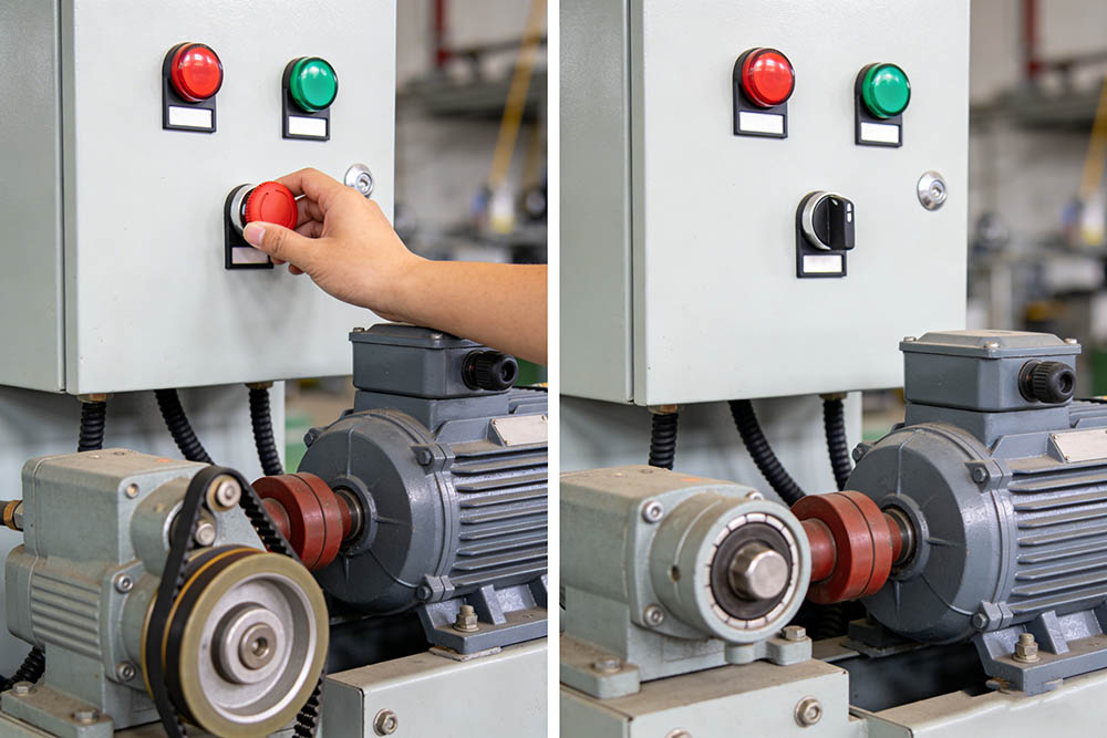
These contacts are typically used in start buttons, relay coils, and other devices that need to be activated by a control signal. For example, a motor start button circuit uses a normally open contact so that the current only flows when the start signal is received, thus activating the motor or system. - Normally Closed Contacts (NC)
These contacts are commonly found in stop buttons, emergency stop switches, and safety interlock circuits. The circuit remains closed by default, allowing power to flow. When the disconnect signal is triggered (such as pressing the stop button or activating a safety feature), the contacts open, interrupting the current and cutting power to the equipment.
For example, in a control panel, a stop button is often connected in series with a normally closed contact. When the button is not pressed, the circuit remains closed, and the system is active. Pressing the button causes the circuit to break, cutting power to the equipment.
Choosing the Right Switch Type for Your Electrical System
In electrical control systems, normally open and normally closed switches are fundamental components used to control the flow of electricity. Understanding their working principles and application scenarios is key to designing and maintaining safe and efficient control circuits. By knowing the differences between normally open and normally closed switches, you can choose the appropriate type for various electrical devices and ensure the stability and safety of your system.
Whether you are designing motor control systems, dealing with complex safety interlocks, or building automation circuits, the choice between normally open and normally closed switches will significantly impact your system’s functionality. KRIPAL offers a wide range of standard switches, relays, and contactors for various industrial and automation control applications. Contact our technical team for personalized advice and quotes to ensure the perfect solution for your project.
Related Resources
Explore News >

How can we assist you?
Tell us a bit more so we can route your request to the right expert.