Search
News
How to read contactor details
Learn how to read contactor details, decode nameplate information, understand technical parameters, and select the right contactor for your application.
![]() December 21, 2025
December 21, 2025
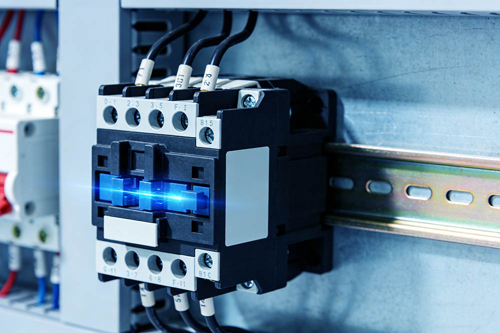
In motor driven equipment such as pumps, compressors, and HVAC systems, stable switching of high current loads is essential for reliable operation. Contactors are responsible for safely connecting and disconnecting these power circuits, directly affecting system performance and safety.
Understanding their structure, working principles, selection methods, and application scenarios is key to proper use. This article explains how contactors function and where they are commonly applied, providing a clear and practical overview.
Key Takeaways
- Understanding the operating principle provides the foundation for correct application and troubleshooting.
- Selecting a contactor according to actual working conditions, including voltage, current, and load type, ensures safe and stable operation.
- Because contactors are widely used in motor control and automation systems, they enable remote and automatic control of high power equipment.
- When contactors are properly maintained and used together with protective devices, their service life can be extended.
Understanding the Nameplate Information
Indicates the maximum operating voltage the contactor is designed to handle. It must match the system voltage. Shows the current the main contacts can carry under specified conditions. Selection should be based on actual load requirements.
Usually marked as 50 Hz or 60 Hz, indicating the applicable power supply standard. Defines the type of load the contactor is suitable for, such as AC1 for resistive loads and AC3 for motor applications.
How to decode the product model number
Identifies the product family or design platform, indicating overall structure and performance level. Represents the current capacity of the contactor, usually corresponding to a specific amperage range.
Indicates the control coil voltage, such as AC 220 V, AC 380 V, or DC 24 V. Shows the number and type of main and auxiliary contacts, such as normally open or normally closed combinations. May indicate additional options such as mechanical interlock, auxiliary modules, or specific certifications.
Contact Configuration
Main Contacts
Main contacts are designed to carry the primary load current in electrical circuits. They are typically used to control high-power equipment like motors, heaters, and other devices that require significant current. These contacts are built to withstand continuous current flow and ensure the safe operation of electrical systems without overheating or causing damage. They are commonly found in industrial applications and power distribution systems.
Auxiliary Contacts
Auxiliary contacts are used in control circuits for signaling, interlocking, or self-holding functions. Unlike main contacts, they handle smaller currents and are often used to signal the status of a system or prevent conflicting actions. These contacts help with functions like keeping a circuit closed once energized or providing feedback to other parts of the control system. They are commonly found in relays, contactors, and circuit breakers.
Normally Open Contacts
These contacts remain open when the coil is de‑energized, meaning no current flows through the circuit. When the contactor is energized and operates, the contacts close mechanically, allowing current to pass through and enabling the connected load to work.
Normally Closed Contacts
These contacts remain closed when the coil is de‑energized, allowing current to flow continuously in the circuit. When the contactor coil is energized, the electromagnetic force will actuate the mechanism, causing the normally closed contacts to open and interrupt the circuit.
Number of Poles
Indicates the number of main power circuits that the contactor can control and switch. Common configurations include single-pole, three-pole, and four-pole, which determine its suitability for different power systems—such as single-phase or three-phase electrical supplies.
What Are the Main Technical Parameters of a Contactor
- This refers to the voltage under which the contactor operates continuously, including both main circuit voltage and control voltage, which must match the power supply system.
- This is the current that the main contacts can carry continuously under specified conditions and is the primary reference for selection.
- This refers to the coil voltage, such as AC 220V or DC 24V, which must match the control power supply so that proper operation is achieved.
- This indicates the type of load, such as AC 1 for resistive loads or AC 3 for motor loads, and it influences allowable current and service life.
- This defines the maximum current that the contactor can safely switch under specified conditions, reflecting its arc resistance and durability.
How to Select a Contactor
Match Load Parameters to Prevent Overload
Once the load type, whether resistive, inductive, or capacitive, has been identified, the rated current of the contactor should be selected according to the load current, while a safety margin of 1.2 to 1.5 times is generally recommended. The rated voltage of the main circuit must also correspond to the supply system.
Determine Coil Parameters to Ensure Stable Operation
The coil type should be selected according to the control power supply, whether AC or DC. At the same time, the coil power and current should be considered so that the control circuit can reliably energize the coil without causing overheating.
Choose Suitable Contacts for Control Requirement
The number and type of contacts, including normally open and normally closed, should be selected according to control logic. If inductive loads are involved, contactors equipped with arc suppression structures should be preferred.
Consider Environment and Service Life
When the operating environment involves high temperature, humidity, or dust, products with suitable protection ratings should be chosen. For high frequency operation, models with longer electrical and mechanical life are recommended.
Confirm Auxiliary Requirements for System Compatibility
If the control system requires auxiliary contacts, interlocking mechanisms, or energy saving coils, these features should be confirmed in advance so that compatibility is ensured.
Applications of Contactors
Motor Control
Contactors are commonly used to control motor start, stop, and forward or reverse operation. When they are combined with other devices, they can enable reduced voltage or star delta starting methods.
Power Distribution and Electrical Control
They are used to control lighting systems, heating equipment, and air conditioning loads so that remote and centralized control can be achieved.
Automation Production Lines
In PLC systems, contactors convert control signals into actual switching actions, enabling coordinated and sequential operation of equipment.
Building and Infrastructure Systems
They are widely used in elevators, pumps, ventilation systems, and fire protection systems, where reliable operation supports building safety and comfort.
New Energy and Charging Equipment
In photovoltaic systems, energy storage systems, and electric vehicle charging stations, contactors are used for power switching and protection control so that system stability is maintained.
How to Maintain a Contactor
The external condition should be checked regularly to ensure that no damage or looseness is present and that wiring terminals are secure. Dust and oil should be removed so that contact performance and mechanical movement are not affected.
Main and auxiliary contacts should be inspected for wear, oxidation, or burning. If damage is minor, polishing may be performed, while severe damage requires replacement. Coil insulation and wiring should be examined to prevent overheating. The iron core surface should be cleaned, and the spring and linkage should move freely. The arc chamber should be checked for integrity.
Maintenance After Abnormal Operation or Long Term Shutdown
If unstable operation, frequent tripping, or contact burning occurs, coil voltage, load current, and contact condition should be examined. When a contactor has been out of service for a long period, insulation and mechanical movement should be checked, and a no load test should be performed before full load operation resumes.
Safety Precautions
Before any maintenance is carried out, the power supply must be disconnected and proper electrical isolation must be ensured. When replacing parts, the specifications must match the original components so that malfunction or safety risks are avoided.
Conclusion
AC contactors are widely used in electrical control systems, and when proper maintenance procedures are followed and safety regulations are observed, reliable performance and extended service life can be achieved.
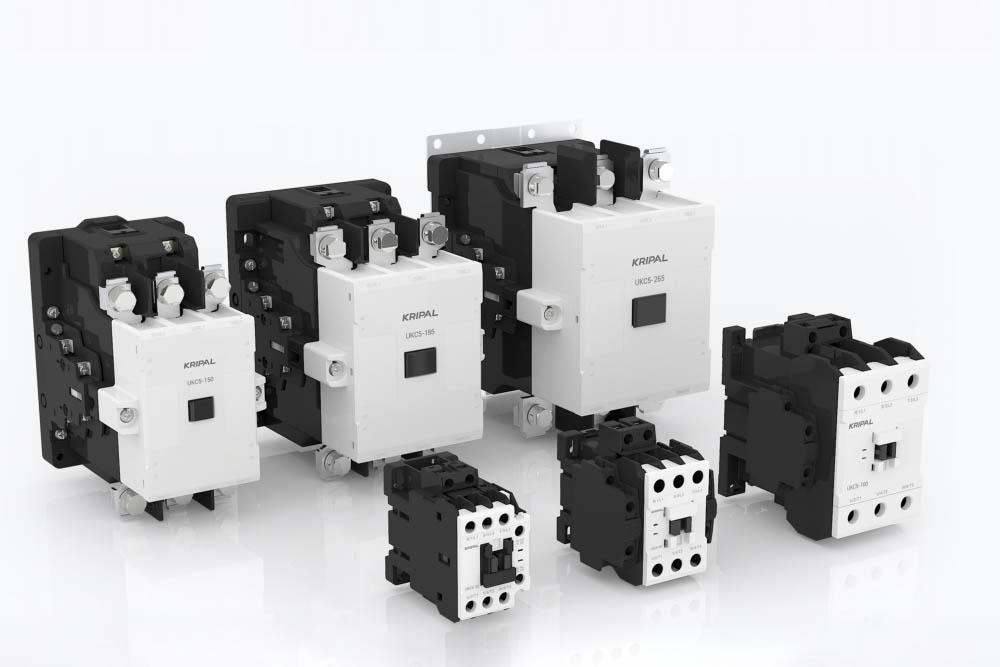
KRIPAL offers a wide range of AC contactors that can address various application needs. Please visit our product page to find a solution that fits your requirements.
FAQs
Q: If a contactor produces a humming sound during operation, should it be stopped immediately for maintenance
Check whether the iron core surface is dirty or corroded. If cleaning does not resolve the issue, inspect the coil voltage and spring condition.
Q: If the contacts show slight burning, must they be replaced immediately
If the damage is minor, polishing can be performed. If burning is severe or contact reliability is affected, replacement is required.
Q: What should be done before restarting a contactor that has been unused for a long time
Inspect insulation and mechanical flexibility, and perform a no load test before reconnecting the load.
Q: When replacing a coil, is matching the voltage sufficient
The voltage and power rating must both match the original specifications so that unstable operation or coil damage is avoided.
Related Resources
Explore News >

How can we assist you?
Tell us a bit more so we can route your request to the right expert.