Search
News
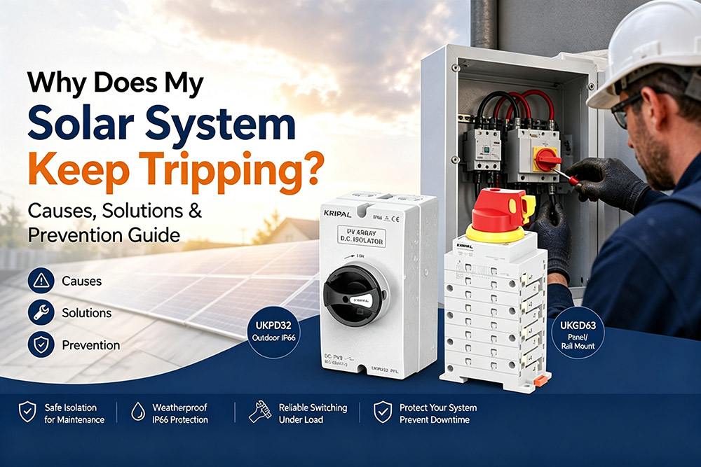
Why Does My Solar System Keep Tripping?
Why does your solar system keep tripping? Learn common causes like grid voltage, inverter faults, DC issues, and how to fix & prevent them effectively.
![]() May 22, 2026
May 22, 2026
A solar power system is designed to operate safely and continuously, converting sunlight into electricity through photovoltaic (PV) modules and inverters. However, in real-world installations, system “tripping” is a common issue faced by homeowners, installers, and EPC engineers.
When a solar system “trips,” it is usually not a malfunction, but a protective response triggered by electrical safety devices or inverter protection logic. These mechanisms disconnect the system when abnormal conditions are detected, preventing equipment damage, fire risk, or electrical hazards.
In this guide, we explain the most common causes of solar system tripping, how to diagnose them correctly, and how proper DC protection design improves long-term reliability.
Key Takeaways
- Solar system tripping is usually caused by protective devices or inverter safety logic
- Common issues include grid voltage fluctuation, insulation failure, wiring faults, and inverter protection triggers
- DC protection devices (MCB, isolator, SPD) each serve different functions and must not be confused
- Proper system design and maintenance significantly reduce downtime
What Does “Solar System Tripping” Mean?
In a photovoltaic installation, solar system tripping refers to the automatic or triggered disconnection of the electrical circuit by protective hardware to halt power generation during an anomaly.
Depending on the nature of the fault, this safety intervention can occur at multiple critical nodes across both the AC and DC sides of the system:
- AC Circuit Breakers (AC MCB / MCCB): Disconnects the system during localized overloads or short circuits on the grid-tied AC line.
- Residual Current Devices (RCD / RCCB): Instantly interrupts the circuit when hazardous leakage current or ground faults are detected.
- Surge Protection Devices (SPD): Diverts high-voltage transient surges (such as indirect lightning strikes) away from sensitive electronics.
- Inverter Internal Protection Circuits: Shuts down power generation based on real-time microchip monitoring of voltage, frequency, and thermal thresholds.
- DC Circuit Protection Devices (DC MCB / Fuses): Clears severe overcurrents or short-circuit faults occurring within the high-voltage DC string array.
Why Does a Solar System Keep Tripping?
Utility Grid Voltage Instability
One of the leading external causes of sudden inverter shutdowns is grid voltage fluctuation. Solar inverters are legally required to operate within strict voltage parameters defined by local utility grid standards. When the local grid voltage moves outside these permissible limits, the inverter activates its grid-protection logic and disconnects from the network.
This issue typically manifests under two specific operational conditions:
- Midday Voltage Rise: During peak solar production hours, hundreds of localized PV systems simultaneously push power back into the utility grid. In areas with high solar penetration or weak distribution infrastructure, this collective input causes the local grid voltage to spike, forcing regional inverters to trip off-line to protect themselves.
- Unstable Utility Infrastructure: In weak or rural grid networks, heavy power demands from nearby industrial equipment or residential air conditioning can cause sudden voltage sags and grid frequency instability, triggering automated inverter shutdowns.
Inverter Internal Protection Triggers
The inverter serves as the intelligent brain of the photovoltaic system, constantly self-diagnosing its internal status and incoming parameters. It will initiate an automatic protective shutdown and log a specific error code due to several internal or environmental faults:
- Overtemperature: Insufficient ventilation or extreme ambient heat causes internal heat sinks to exceed safe limits, triggering thermal throttling or a complete protective shutdown.
- Grid Frequency Instability: Deviations from standard grid frequencies (50Hz or 60Hz) force the inverter to disconnect to maintain anti-islanding safety compliance.
- Internal Component Faults: Relays sticking, computational communication errors between internal control boards, or degradation of aging capacitors.
- MPPT Tracking Anomalies: Drastic changes in DC input string voltages that confuse the Maximum Power Point Tracking (MPPT) algorithm.
Repeated inverter shutdowns should never be ignored as a simple “glitch”—they represent a system-wide diagnostic warning that requires immediate technical inspection.
DC Side Faults (Insulation Degradation & Leakage Current)
Photovoltaic arrays frequently operate at high DC voltages, commonly ranging from 600V up to 1500V in modern commercial and industrial configurations. Over time, the physical integrity of the DC side can break down due to prolonged environmental exposure, leading to dangerous insulation failures.
Common vectors for DC insulation faults include:
- Cable Insulation Aging: Constant exposure to high UV radiation and extreme thermal cycling cracking or wearing down the outer protective jacket of solar cables.
- Moisture Ingress: Rainwater, heavy morning dew, or coastal humidity seeping into poorly sealed MC4 connectors, string junction boxes, or roof penetrations.
- Mechanical Damage: Cables rubbing against sharp metal edges of the solar mounting racking or damage caused by nesting pests.
When moisture creates a conductive path between a live DC conductor and the grounded aluminum solar racking, a ground fault occurs. The inverter’s highly sensitive internal insulation monitoring systems or an external RCD will instantly detect this hazardous leakage current and disconnect the system to avert severe electric shock or electrical fire risks.
Wiring Faults and Loose Connections
In solar engineering, a secure physical connection is paramount. High-voltage DC circuits are highly susceptible to resistance localized issues. Poor or loose wiring terminations within the DC loop act as immediate points of electrical failure, leading to:
- Series Electric Arcing: Loose contacts create a minute air gap where high-voltage DC electricity can jump, generating intense localized temperatures that can exceed several thousand degrees Celsius, posing an immediate fire hazard.
- Intermittent Power Losses: Thermal expansion and contraction can cause loose wires to separate slightly under load, resulting in sporadic, hard-to-diagnose inverter shutdowns.
- Extreme Terminal Overheating: Increased resistance at loose terminals directly generates heat, which can quickly melt plastic components within junction boxes, combiners, or inverter terminal blocks.
The most common points of connection failure in the field are poorly crimped MC4 connectors, loose terminal blocks inside combiner boxes, and incorrectly torqued DC inputs.
DC Protection Device Misapplication
In real-world engineering practices, a significant percentage of “system tripping” complaints do not stem from actual wiring faults or grid instability. Instead, they are caused by incorrect selection, misapplication, or fundamental misunderstandings of DC protection devices.
Many installers treat all DC components on the wall as interchangeable safety switches, which is a dangerous misconception that compromises both system reliability and safety.
To design and maintain a stable photovoltaic system, engineers must maintain a strict functional distinction between these three essential components:
| Device Type | Core Engineering Function | Operation / Tripping Mechanism | Primary PV Application | Reusable? |
| DC Isolator Switch | Safety Isolation
Safely isolates high-voltage DC arrays and extinguishes dangerous electric arcs under heavy load. |
Manual Only
No automatic tripping mechanism; does not react to overcurrents or short circuits. |
Routine system maintenance, system troubleshooting, and emergency manual shutdown zones. | Yes
Repeated manual switching. |
| DC MCB | Fault Protection | Automatic Tripping
Instantly snaps open via thermal-magnetic or electronic trip units during faults. |
Circuit protection against severe overcurrents, string overloads, and line short circuits. | Yes
Can be manually reset after the fault is cleared. |
| DC Fuse | Sacrificial Protection | Automatic Blowing
The internal sacrificial element melts when fault currents exceed thresholds. |
Multi-string combiner boxes; isolates a single faulty string from feeding back into the array. | No
One-time protection; must be physically replaced after blowing. |
Deploying these devices incorrectly, or failing to properly coordinate their ratings, inevitably leads to continuous nuisance shutdowns, accelerated component degradation, or catastrophic electrical safety failures under fault conditions.
Explore our professional range of KRIPAL Solar DC Isolator Switches to download official datasheets or request a wholesale quote.
How to Diagnose Solar System Tripping
Check the Inverter Fault Codes
Fault codes often provide direct information about the source of the problem. Most modern inverters include a display screen or monitoring application that records detailed alarm information.
Conditions such as overvoltage, undervoltage, insulation faults, and temperature issues are usually associated with specific codes. By reviewing the fault code descriptions provided by the manufacturer, users can narrow down the possible causes more efficiently.
Identify the Acted Protective Device
Determining exactly which piece of hardware physically tripped or opened provides a direct map to the fault type:
- AC Breaker Tripped: Points directly to a grid-side overload, utility fault, or short circuit in the AC run.
- DC MCB Tripped: Confirms a catastrophic fault on the PV side, such as a direct short circuit between strings or a severe overcurrent event.
- RCD Tripped: Clearly indicates a leakage current issue or a major insulation breakdown somewhere within the system grounding path.
- Inverter Blank / Shut Down (But No Breakers Tripped): Indicates an internal inverter safety parameter trigger or utility grid parameter outage.
Analyze Environmental and Timing Patterns
Correlating the exact timing of the shutdown events with local weather conditions can reveal hidden system vulnerabilities:
- Midday Tripping (11 AM – 2 PM): Typically points to grid voltage spikes caused by peak regional solar export, or inverter thermal overloading.
- Rainy / High Humidity Tripping: Strong indicator of moisture ingress into outdoor MC4 connectors or cracked cable insulation creating a ground fault path.
- Hot Weather Tripping: Suggests poor inverter ventilation, cooling fan failures, or improper mounting placement in direct sunlight.
- Random, Erratic Tripping: Strongly points to a physical loose connection or a deteriorating terminal within the AC or DC distribution blocks.
Review Comprehensive Monitoring Analytics
Utilize the smart solar monitoring software to analyze historical data trends leading up to the trip event. Keep a close eye out for sudden AC voltage spikes, erratic DC string current drops, or gradual declines in insulation resistance values over several weeks.
How to Fix a Tripping Solar System?
Once a definitive diagnosis is established, technical teams can apply targeted engineering solutions to restore continuous power generation safely.
Resolve Voltage Related Issues
If abnormal grid voltage is causing the system to trip, contact the utility provider to verify power quality. If the issue originates from the local grid, adjusting inverter settings, updating inverter firmware, or installing voltage regulation equipment may help improve system stability. Larger installations may also benefit from optimized grid connection strategies.
Inspect and Repair the Inverter
When an inverter repeatedly reports faults, review the error history and follow the manufacturer’s troubleshooting recommendations. If overheating is the cause, cleaning ventilation openings or improving airflow may solve the problem. If internal components have failed, professional repair or replacement is recommended to avoid further damage.
Rectify DC Wiring and Insulation Failures
To clear persistent ground faults and insulation alarms on the PV side:
- Isolate individual DC strings and utilize a Megohmmeter (Megger) to systematically test insulation resistance to ground.
- Completely replace any weathered, UV-damaged, or rodent-chewed DC cabling.
- Cut away improperly crimped or moisture-corroded MC4 connectors and re-crimp premium, watertight replacements using professional tooling.
- Open outdoor junction boxes and combiner enclosures to dry out moisture, clean out corrosion, and replace compromised rubber gaskets.
Upgrade and Correct the DC Protection Architecture
A highly secure, robust photovoltaic system must utilize a properly segregated and rated DC distribution architecture. Ensure your system layout features:
- Dedicated, environment-appropriate DC Isolator Switches to facilitate safe manual load-breaking during maintenance.
- Properly calculated DC MCBs or fuses to provide rapid, automatic thermal-magnetic protection against localized short circuits.
- Type 2 Surge Protection Devices (SPDs) bound to a verified ground terminal to neutralize lightning-induced transient voltages.
- Engineered string layouts that stay well within the maximum DC input voltage and current ratings of the chosen inverter.
How to Prevent Frequent Solar System Tripping?
The long-term reliability and return on investment (ROI) of a commercial or residential solar installation depend heavily on preventative engineering and maintenance.
Implement a Strict Annual Maintenance Schedule
Do not wait for a trip event to inspect the array. At least once a year, a professional solar technician should:
- Conduct megohm testing on all DC and AC loops to verify cable insulation integrity.
- Utilize a calibrated torque wrench to verify that all electrical terminal screws (within combiners, isolators, and breakers) remain tightened to manufacturer specifications.
- Perform thermal imaging (thermography) scans across all MC4 connectors, combiner boxes, and switches under full load to spot hidden localized hotspots before they trigger a fault.
- Verify the overall continuity and low resistance of the entire system earthing and grounding grid.
Source High-Quality, Certified Electrical Protection Gear
Cutting costs on structural electrical protection components is a primary cause of future nuisance tripping, premature system aging, and dangerous equipment failures.
Always verify that your DC switches, breakers, and surge protectors are sourced from reputable manufacturers and hold recognized global certifications (such as TUV, CE, SAA, and UL). High-quality components feature superior materials, reliable contact mechanisms, and advanced arc-extinguishing technology designed to operate under harsh outdoor environments for decades.
Elevate Environmental Protection Barriers
Protect your system infrastructure from the degrading effects of outdoor exposure:
- Ensure all outdoor electrical enclosures maintain a verified IP66 waterproof and dustproof rating.
- Route outdoor DC and AC wiring runs through high-impact, UV-resistant electrical conduits rather than leaving wires exposed to direct solar radiation on the roof.
- Keep the immediate area around outdoor components clear of heavy vegetation, nesting birds, or debris that could block critical airflow or cause physical cable damage.
Optimize System Engineering and Design (EPC Level)
For commercial and utility-scale EPC projects, engineering accuracy during the drafting phase prevents systemic tripping:
- Accurate DC/AC Ratio Calculation: Ensure the total DC array capacity does not excessively overload the inverter’s maximum input capabilities during peak cold, sunny days (when solar panel voltage naturally increases).
- Segmented Protection Zones: Implement localized, independent DC combiner isolation zones so that a single fault within one string array can be isolated cleanly without taking down the entire multi-megawatt plant.
- Proper Thermal Dissipation Calculation: Ensure electrical cabinets and indoor inverter rooms feature calculated forced-air ventilation or air-conditioning systems to prevent cascading thermal shutdowns during extreme summer peaks.
Why DC Protection Devices Matter in Solar Safety
In modern photovoltaic engineering, the implementation of dedicated DC protection is not an optional add-on—it represents the foundational layer of system safety and asset protection.
Because solar panel strings operate as continuous current sources, they generate hazardous high-voltage DC electricity the moment sunlight hits the modules. Unlike AC electricity, which naturally crosses a zero-voltage point 50 or 60 times a second (making it relatively easy to extinguish an electric arc), a high-voltage DC current flows continuously.
Once a DC electric arc forms—whether due to a loose wire or an insulation failure—it will not self-extinguish. It will burn continuously, melting components and generating extreme temperatures that can easily cause severe structural fires.
A meticulously designed system addresses this risk by enforcing a strict division of labor between its components:
- Inverters manage the intelligent grid interface, power conversion, and digital system safety tracking.
- DC MCBs stand ready as automatic guardians, snapping open instantly to isolate devastating short circuits and overcurrent faults.
- DC Isolators put absolute manual control back into the hands of the maintenance crew, guaranteeing that a field engineer can completely and safely cut off incoming high-voltage DC power before working on the system.
Confusing these specialized roles or cutting corners on component quality is one of the most widespread root causes behind troubleshooting failures and catastrophic field losses.
Conclusion
A solar system trip is ultimately a sign that built-in safety protection layers are functioning exactly as intended to shield your property and equipment from electrical anomalies. However, frequent or repeated tripping points directly to deep, unresolved electrical or structural design flaws that must be addressed systematically.
By adopting a structured diagnostic approach—tracking down inverter error codes, identifying whether the AC or DC side protection has acted, verifying physical wiring tightness, and inspecting insulation integrity—operators can quickly locate and neutralize faults.
Investing in robust system design and premium, precisely categorized components—especially within the critical DC protection network—is the ultimate way to eliminate nuisance downtime, protect on-site personnel, and guarantee the safe, high-yield operation of your solar asset for years to come.
FAQs
Q Why does my solar inverter keep tripping exactly at midday?
This is almost always triggered by utility grid overvoltage. Midday represents the absolute peak of solar generation. When numerous solar arrays in your local area export maximum power back into a constrained or weak utility network simultaneously, the localized grid voltage spikes. Once it exceeds the inverter’s pre-programmed safety threshold, the inverter will automatically trip off-line to protect its internal circuitry.
Q Is a constantly tripping solar system dangerous?
The act of tripping itself is a safe, protective response designed to prevent danger. However, the underlying condition causing the continuous trips (such as progressive cable insulation degradation, un-extinguished series arcing, or severe terminal overheating) is highly dangerous and can escalate into an electrical fire or severe shock hazard if left unaddressed by professional engineers.
Q What is the fundamental difference between AC and DC side tripping?
- AC Side Tripping: Triggered by faults occurring between the inverter output and the utility grid. Common causes include grid voltage sags/swells, grid frequency drift, building overloads, or residual ground-leakage currents flowing through external RCDs.
- DC Side Tripping: Triggered by faults within the high-voltage solar panel array down to the inverter input. It is caused by issues like short circuits between parallel strings, crushed cabling, moisture in MC4 connectors, or a triggered DC MCB clearing localized overcurrent events.
Q Can an incorrectly chosen DC isolator switch cause a system to trip?
No, a pure manual DC isolator switch cannot automatically trip because it lacks any internal thermal-magnetic or electronic trip units. However, if a low-quality, poorly rated, or incorrectly installed isolator switch is utilized, its internal contacts can pit, degrade, or loosen over time. This increases contact resistance, generates immense localized heat, and creates intermittent micro-disconnections that the inverter interprets as an unstable input fault, causing the inverter to shut down..
Q How can I completely eliminate solar system tripping over a 20-year lifespan?
Long-term stability requires a multi-layered engineering approach:
- Implement a rigorous, coordinated DC protection architecture using distinct components for distinct jobs (e.g., manual isolators for safe isolation and DC MCBs for overcurrent faults).
- Mandate an expert annual maintenance check to torque terminals, inspect gaskets, and perform infrared thermal scans.
- Insist on sourcing premium, globally certified components—such as the KRIPAL UKPD32, UKGD63, and UKB7Z series—specifically engineered to handle high-voltage DC load-breaking and severe outdoor environmental extremes.
Related Resources
Explore News >

How can we assist you?
Tell us a bit more so we can route your request to the right expert.