Search
News
What are Normally Closed vs Normally Open Switch?
Avoid sizing errors in Star-Delta motor starters. Learn precise rules for Main, Star & Delta contactor ratings and thermal relay selection for your Star Delta starter.
![]() January 13, 2026
January 13, 2026
In electrical control systems, “Normally Open” (NO) and “Normally Closed” (NC) are core terms used to describe the default state of a switch or contact when not subjected to external force.
While they may appear similar, there are actually many differences, and they utilize their respective advantages in different application scenarios. Understanding their differences and functions can help you choose the suitable switch type for your project or application.
This article will provide an in-depth analysis of the similarities and differences between these two proximity switches, helping you better understand their characteristics and make accurate choices in practical applications.
Basic Principles of Switch Operation
Switches serve as control devices to control the flow of current. The basic working principle of a switch is to block or connect a circuit.
The core lies in two basic states:
Normally Open and Normally Closed. In the Normally Open state, the switch prevents current from passing, creating an open circuit.
Conversely, in the Normally Closed state, the switch allows current to pass, forming a closed circuit. This simple concept forms the foundation of various switch designs and applications.
Mechanical switches operate by toggling contacts, which physically opens or closes metal contacts. This alters the connection within the circuit, thereby allowing or preventing the flow of current.
Normally Open (NO) Switches
A Normally Open switch refers to a switch device where the internal contacts are separated by default in their natural resting state. This means that without external force, the circuit is broken, current cannot pass and the device remains off or silent. Only when the user presses a button or a sensor is triggered do the contacts momentarily close, completing the circuit to let current flow. Once the force is removed, the switch usually springs back to its initial open state.
Typical Applications: Start buttons, photoelectric sensors, holding contacts in self-locking circuits.
Common NO Switch Types (By Operation)
Although the internal logic is “Normally Open,” the physical forms vary:
- Push Button: The most typical momentary control; press to connect.
- Toggle/Rocker Switch: Common in home lighting; closes the circuit when flipped to the “On” position.
- Tactile Switch: Mouse clicks or remote control buttons; provides crisp click feedback.
- Rotary Switch: Connects specific contacts by rotating a dial.
Normally Open (NO) Pros and Cons
✅ Energy Saving: Consumes no power in the standby state.
✅ Prevents Accidental Operation: High safety for non-emergency devices as it requires active operation to start.
❌ Requires Active Operation: Not suitable for devices that need to run by default.
Normally Closed (NC) Switches
In the resting state without external force, the contacts are touching and closed by default. This means the circuit is connected by default, allowing current to flow freely, and the device is in a powered or monitoring state. When the switch is triggered by external force or pressed, the contacts separate, breaking the circuit and cutting off the current. This “press to break” logic makes NC switches the top choice for safety protection fields.
Typical Applications: Emergency stop buttons, protection contacts in thermal overload relays, safety door interlock switches.
Common NC Switch Variants (By Trigger Medium)
- NC Push Button: The most basic form. The standard configuration for “Emergency Stop” buttons.
- Thermal Switch: A temperature-sensitive protection device that disconnects when overheated.
- Reed Switch: Controlled by magnetic fields. Contacts separate when magnets move (common in anti-theft alarms).
- Pressure Switch: Disconnects the circuit when pressure reaches a set limit to stop pumps/motors and prevent overpressure.
- Float Switch: Used for liquid level control. Disconnects when the liquid level rises to a warning line to prevent overflow.
Normally Closed (NC): Pros and Cons
✅ Safety & Limit Use: The preferred choice for safety devices and limit switches. Cutting power upon trigger is generally safer than connecting it.
✅ “Fail-Safe” Capability: The biggest advantage over NO switches. If a wire breaks accidentally, the system detects it as a “triggered” circuit open and stops the machine immediately.
❌ Risk of Mechanical Wear: Many NC switches require physical contact, leading to wear from impact and electrical arcing.
❌ Limited Installation: Requires precise positioning to ensure physical contact or medium triggering (pressure/magnetic), otherwise it risks failure.
How to Distinguish Quickly?
| Feature | Normally Open (NO) | Normally Closed (NC) |
| Full Name | Normally Open | Normally Closed |
| Visual Symbol | Like a broken bridge (Open) | Like a connected bridge (Closed) |
| Default State (Resting) | Circuit Disconnected (OFF) | Circuit Connected (ON) |
| When Activated | Current Flows (ON) | Current Stops (OFF) |
| Simple Rule | “Push to Connect”
(Connects on action) |
“Push to Break”
(Disconnects on action) |
| Best Applications | Start buttons, Doorbells, Keyboards | Emergency Stops (E-Stop), Safety Monitoring, Fail-safe Protection |
The Core Role of NO and NC in Contactors
Contactors serve as the heavy-lifters of industrial automation, using electromagnetic force to switch high-power loads like motors, but their true intelligence lies within their auxiliary contacts. The Normally Open (NO) auxiliary contact is the backbone of the “self-holding” (or latching) logic. In a standard start-stop circuit, the NO contact is wired in parallel with the start button.
Once the contactor energizes, this contact closes to bridge the circuit, ensuring the coil remains powered and the machine keeps running even after the operator releases the momentary start button. Additionally, NO contacts are commonly used to trigger green “Run” indicator lights or send active status signals to a central control system.
Conversely, Normally Closed (NC) auxiliary contacts are critical for safety logic and conflict prevention, most notably in “interlocking” circuits. For instance, in a motor reversing system, the NC contact of the forward contactor is wired directly into the reverse contactor’s control loop.
This creates a physical safety lock: if the forward contactor is active, its NC contact opens to cut power to the reverse coil, making it electrically impossible for both directions to engage simultaneously and preventing catastrophic short circuits. Beyond safety, NC contacts are also used to power red “Stop” or “Standby” indicators, providing visual feedback that the equipment is resting.
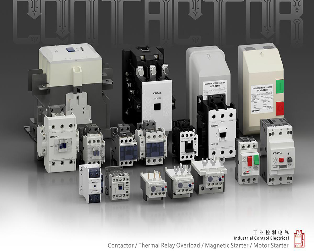
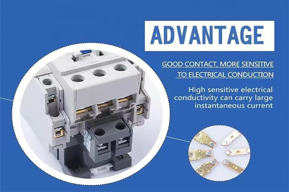
Contact Configuration Advantages of KRIPAL Contactors
The KRIPAL series contactors offer versatile combinations of main and auxiliary contacts to cater to diverse control scenarios:
| Contactor Type | Configuration | Main Contacts | Auxiliary Contacts | Key Applications |
| 3-Pole (3P) | Standard Motor Control | 3NO (For L1, L2, L3) |
1NO + 1NC (Side-mounted) • 1NO: For self-locking/latching circuits. • 1NC: For status indication or interlocking. |
• Standard 3-phase motors • Water pumps • Fans • General industrial loads |
| 4-Pole (4P) | Standard Isolation | 4NO | Configurable / Add-on | • Systems requiring Neutral (N) line disconnection • IT earthing systems • Medical facilities • Data centers |
| Switching / Reversing | 2NO + 2NC | Configurable / Add-on | • Power transfer systems (ATS) • Dual-load switching • Test bench switching loops |
Practical Application Examples in Control Circuits
Example 1: Motor Start/Stop Self-Locking Circuit (Using KRIPAL 3P Contactor)
- Start Button: Normally Open (NO) — Momentary action.
- Stop Button: Normally Closed (NC) — Safety priority.
- Contactor Auxiliary Contact: Uses the built-in 1NO contact to achieve “Self-Locking” (or Latching).
- Logic: Once the Start button is pressed, the coil energizes. Even after the button is released, the coil remains powered through this parallel NO contact.
- Safety Design: The Stop button is wired in series within the control circuit. Any physical disconnection (including pressing the Emergency Stop) immediately cuts power to the coil, stopping the motor.
Example 2: Dual Motor Interlock Control (Forward/Reverse)
- Setup: Uses two KRIPAL contactors, each utilizing its NC Auxiliary Contact wired in series into the opposing contactor’s start circuit.
- Logic: When Motor A is running, its NC contact opens physically. This cuts the circuit for Motor B, preventing it from starting. This “Electrical Interlock” prevents short circuits or mechanical conflicts.
How to Identify and Test NO/NC Contacts?
1. Circuit Diagram Symbols
- NO: ─○─ Often represented as an open gap or empty circle.
- NC: ─●─ Often represented with a diagonal slash or solid circle.
2. Multimeter Test (Continuity Mode)
- NO: No beep when idle (Circuit is Open/OL).
- NC: Beeps continuously when idle (Circuit is Closed/Conductive).
3. Visual Inspection on Contactor
KRIPAL contactors feature clear markings on the side for quick wiring identification:
- 13–14: Standard terminal numbers for NO (Normally Open).
- 21–22: Standard terminal numbers for NC (Normally Closed).
Building Intelligent Control with Reliable Contacts
In the realm of electrical automation, while a contact point may be small, it carries immense responsibility. KRIPAL deeply understands this critical role, which is why we prioritize clear identification, standardized interfaces, and plug-and-play auxiliary contact configurations in every design.
Whether you are managing standard three-phase motor controls or engineering complex power switching systems, KRIPAL contactors deliver the performance you need. [Explore the full range of KRIPAL Contactors] today to find the perfect configuration for your project, or [Contact Our Technical Team] for a personalized consultation and quote.
Related Resources
Explore News >

How can we assist you?
Tell us a bit more so we can route your request to the right expert.