In this comprehensive guide, we break down the core working principles, wiring logic, key application fields, and precise technical specifications of our two flagship product series—the submersible UKY-1/2/3 Series and the top-mounted UKY70-AB—to help you make the perfect sourcing decision.
Core Working Principles: How They Control Liquid Levels
At their core, float switches function as displacement or angle-sensitive liquid level sensors. While their core objective is identical—opening or closing a circuit based on fluid height—their internal mechanical architectures differ significantly to serve different environments:
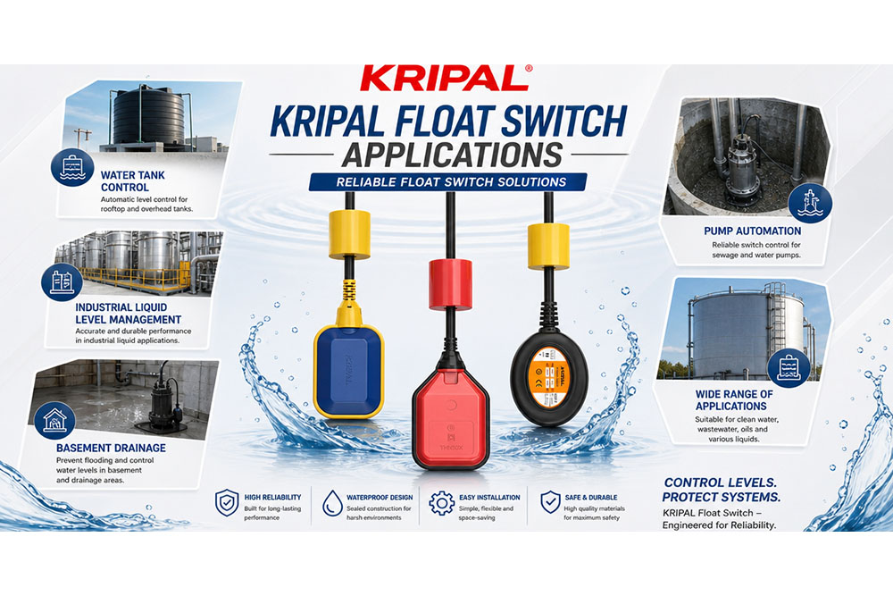
Submersible Cable Float Switches (UKY-1 / UKY-2 / UKY-3)
This series features a fully sealed, buoyant plastic chamber housing a guided metallic track and a microswitch, suspended directly in the liquid by a heavy-duty waterproof cable. As the liquid level shifts, the floating body tilts dynamically.
Once the tilt angle crosses a specific critical threshold (typically $\pm 28^\circ$ to $\pm 45^\circ$), an internal precision steel ball rolls down the guided track. The weight of this ball depresses a mechanical lever, altering the contact status of the microswitch.
Top-Mounted Liquid Level Switches (UKY70-AB)
The UKY70-AB features a static, surface-mounted design. The electrical switch mechanism is completely contained inside a protected housing that sits outside and on top of the tank or reservoir.
Two balanced, non-buoyant heavy weights are suspended into the liquid via a high-tensile nylon cord. This system functions entirely through mechanical tension and buoyancy changes:
- When the water level dropsbelow the lower weight, the full gravitational pull of both weights exerts downward tension on the cord, pulling down an internal spring-loaded lever mechanism to toggle the electrical contacts.
- When the water level risesand submerges both weights, the fluid’s buoyant force counterbalances the weight, releasing the cord tension. The internal heavy-duty spring pulls the mechanism back up, reversing the contact state.
Wiring Logic & Control Modes: Avoiding On-Site Failures
Many sourcing agents misinterpret the 3-wire or dual-terminal system logic, which directly leads to reversed operation failures during on-site commissioning. Understanding the distinct terminal combinations is vital for system safety:
Submersible UKY-1/2/3 3-Wire System Matrix
| Control Mode |
Wire Combination |
Float Position (Liquid Level) |
Contact Status |
Pump Operation |
| Emptying / Drainage Mode (Pump Down) |
Black (COM) + Blue (NO) |
High Position (Floating) |
ON (Connected) |
Pump Starts (Drains water out) |
| Emptying / Drainage Mode (Pump Down) |
Black (COM) + Blue (NO) |
Low Position (Hanging) |
OFF (Disconnected) |
Pump Stops (Dry-run protection) |
| Filling Mode (Pump Up) |
Black (COM) + Brown (NC) |
Low Position (Hanging) |
ON (Connected) |
Pump Starts (Fills water in) |
| Filling Mode (Pump Up) |
Black (COM) + Brown (NC) |
High Position (Floating) |
OFF (Disconnected) |
Pump Stops (Overfill protection) |
⚠️ Unused Wire Safety Note: Whichever wire is left unused (e.g., the Brown wire in Drainage mode) must be insulated individually using heat-shrink tubing or waterproof electrical terminal caps. Leaving raw copper wire exposed inside a humid environment will result in moisture bridging, causing dangerous ground faults and phantom controller tripping.
Top-Mounted UKY70-AB Dual-Circuit A/B Terminal Matrix
The UKY70-AB features a dual-circuit terminal block that allows a single switch to execute either function by switching terminal pins. It allows highly adjustable liquid level differentials ranging from 0.2m to 5m.
- Terminal A (Filling / Water-In / Pump Up): Connects the circuit at low water level to start the pump, and cuts power at high water level to prevent overfill.
- Terminal B (Drainage / Emptying / Pump Down): Connects the circuit at high water level to start the pump, and cuts power at low water level to prevent pump dry-running.
Comprehensive Product Showdown & Technical Datasheet
Different environments demand different physical and electrical specifications. Selecting the wrong architecture compromises the safety of the entire installation. Below is the official technical datasheet comparison:
Comprehensive Technical Specification Table
| Technical Dimension |
UKY-1 / UKY-2 / UKY-3 Series (Submersible) |
UKY70-AB Series (Top-Mounted / Heavy-Weight) |
| Product Structure |
Sealed float body with heavy-duty waterproof cable. |
Stationary top-mounting base with a suspended dual-weight system. |
| Rated Voltage |
250V (380V) / 120V AC |
250V (380V) / 120V AC |
| Rated Current |
16A(8A), 10A(8A), 10A(4A) |
15A(3A) |
| Operating Temperature |
0°C < Water Temp $\le$ 80°C (32°F to 176°F) |
5°C to 60°C (41°F to 140°F) |
| Mechanical Lifespan |
$\ge$ 100,000 Cycles |
$\ge$ 1,000,000 Cycles |
| Electrical Lifespan |
$\ge$ 50,000 Cycles |
$\ge$ 100,000 Cycles |
| Ingress Protection |
IP68CS (Premium submersible, permanently underwater). |
IP23CS (Splash-proof housing, must be mounted outside the liquid). |
| Primary Advantage |
Extremely quick installation and highly flexible level control via adjustable counterweights. |
Isolated Control Mechanism: Electrical parts stay completely dry, isolated from corrosive fumes and turbulent liquids. |
| Target Application Fields |
Sewage pits, deep wells, open reservoirs, municipal drainage, and stormwater pump stations. |
Clean water pools, water towers, industrial cooling towers, indoor condensate tanks, or sewage wells. |
Engineering Deep-Dive: Rated Voltage & Current Specifications
When reviewing a KRIPAL datasheet, navigating the electrical thresholds correctly is paramount to avoiding catastrophic control panel burnouts. Here is the explicit engineering breakdown of our specifications:
⚡ Deep-Dive 1: Rated Voltage Exceeded Risks
The Rated Voltage (250V / 380V / 120V AC) defines the maximum nominal alternating current voltage where the internal microswitch contacts and insulation can safely operate.
- 250V AC: The global standard for domestic and industrial single-phase 220V–240V power grids.
- (380V AC) Parentheses Value: The value “380V” refers to the maximum control circuit voltage specified in the product technical datasheet. For motor applications, the float switch should only be used as a control device and should not be connected directly to the motor power circuit.
- 120V AC: Engineered specifically for American and Japanese low-voltage grid systems (110V/120V system compliance), optimized for export markets.
- The Rule of Voltage: Exceeding these rated voltages triggers severe electrical arcing that welds contacts shut or causes dielectric breakdown of the insulation. Operating below the rated voltage is completely safe; it simply reduces the proportional load wattage.
🔌 Deep-Dive 2: Rated Current Format — Resistive vs. Inductive Load
Our current ratings are always displayed as Normal Current (Parentheses Current), such as 16A(8A) or 15A(3A). This represents two entirely different electrical load profiles:
- Resistive Load (Value Outside Parentheses): Applies to devices with zero startup inrush current, such as electric water heaters, heating rods, and incandescent indicator filaments.
- Inductive Load (Value Inside Parentheses): Applies directly to electric motors, water pumps, solenoids, and magnetic coils. Due to the physics of electromagnetic induction, motors experience a massive inrush (locked-rotor) current during startup that is 3 to 7 times higher than their nominal running current. Because of this destructive surge, the allowable direct current capacity drops drastically.
Core Selection & Wiring Practical Rules
To eliminate terminal burnouts and warranty claims, engineers and contractors must enforce these two operational constraints on-site:
[ Float Switch ] —> Controls —> [ AC Contactor Coil ] —> Drives —> [ High-Power Pump ]
- High-Power Pumps (750W / 1HP) Must Use AC Contactors: For both the Submersible (UKY-1/2/3) and Top-Mounted (UKY70-AB) series, never wire a high-power pump directly in series with the switch. The float switch must be wired to drive the command coil of an AC Contactor, letting the heavy-duty contactor points handle the raw motor current and prevent contact arcing.
- Voltage Application Alignment: For domestic or European projects utilizing 220V lines, select the 250V parameter configuration. For product export targeting North America, Canada, or Japan running 110V/120V grids, always specify the 120V AC system model.
Deep-Dive B2B Technical FAQ
Q1 Why does my pump chatter or turn on and off rapidly when using a cable float switch?
This is called “pump short-cycling,” and it happens for two reasons: either the liquid surface is highly turbulent, or the counterweight is placed too close to the float body (creating an extremely narrow activation differential). To fix this, move the counterweight further back along the cable to increase the control envelope radius, or install a stilling well (a perforated PVC pipe around the float) to isolate the switch from surface ripples.
Q2 Can KRIPAL float switches handle highly acidic or alkaline wastewater?
Our standard models are molded from premium Polypropylene (PP) and paired with specialized PVC or Neoprene rubber cables, which offer excellent chemical resistance against standard municipal sewage, mild acids, and bases within their specific operating temperature limits.
Q3 If my pump runs on 3-phase 380V power, can I wire a KRIPAL float switch directly to it?
Absolutely not. Doing so may result in severe contact arcing, welding, premature failure, or damage to the switch contacts and create a severe phase-to-phase short circuit. While the technical data notes 380V short-term isolation capability, these switches are strictly designed for single-phase command circuits. You must wire the float switch to the command coil (A1/A2 terminals) of a 3-phase AC Contactor or a dedicated motor starter panel.
Q4 How do I adjust the liquid level range on a top-mounted UKY70-AB model?
The control range on the UKY70-AB is adjusted manually by altering the physical spacing between the two suspended weights along the high-tensile nylon cord. The upper weight determines the high-water stop/start threshold, while the lower weight dictates the low-water action point. Simply slide the weights to your desired heights and secure them with the integrated retention clips to lock in your custom liquid level envelope.
Why Global B2B Buyers Choose KRIPAL ELECTRIC
With over three decades of focused R&D and automated manufacturing in the low-voltage electrical field, KRIPAL is more than a supplier—we are your engineering partner.
- Pump Manufacturers (OEMs): Our clear-cut inductive load specifications fit perfectly into standard pump control packages, drastically reducing your post-sale warranty claims.
- Engineering Contractors: Backed by premium mechanical lifespans ($\ge$ 1,000,000 cycles for UKY70-AB) and certified builds, our level switches pass strict project site inspections and handovers seamlessly.
- International Traders: With full CE Certification, rigorous QA protocols, and extensive electrical cycle life, KRIPAL guarantees strong market reputation and high repeat-order rates.
Contact Our Engineering Team Today
Need customized cable lengths (heavy-duty PVC or Neoprene rubber), or bulk OEM pricing?


 Search