Search
News
A Comprehensive Guide to AC Contactors
Master AC contactors with this complete guide. Learn how they work, key specs for selection, step-by-step testing, safe replacement procedures for HVAC & industrial systems.
![]() January 07, 2026
January 07, 2026
When starting an air conditioner or an industrial motor, there is an unsung “hero” that ensures everything operates safely and efficiently. This device is the AC contactor that is a compact yet powerful component responsible for managing the power supply to large electrical equipment.
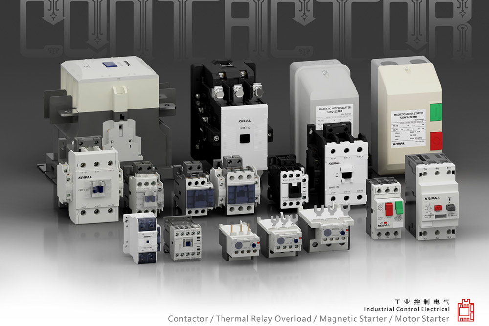
These electromechanical devices act as remote-controlled switches capable of handling currents up to 800A and voltages up to 690V. Their applications are vast, ranging from heavy-duty factory motors to residential cooling systems.
However, if this critical component fails, entire systems can grind to a halt. This guide covers everything you need to know: what an AC contactor is, how it works, how to test it, replacement procedures, and more.
What is an AC Contactor?
An AC contactor is an electromechanical device designed to bridge or interrupt high-current electrical circuits using electromagnetism. It is primarily used to switch high-power AC loads. Unlike manual switches, a contactor is operated by a low-voltage control signal, allowing for the safe, remote operation of high-voltage industrial and commercial equipment.
The Working Principle
An AC contactor operates through the synergy of magnetic force and spring tension.
When a control voltage is applied to the internal coil, it generates a magnetic field that pulls a movable armature toward a fixed core. This movement forces the main contacts to close, completing the circuit and allowing electricity to flow from the power source to the load. Once power is removed from the coil, the magnetic field collapses, and heavy-duty internal springs push the contacts back to their original position, safely breaking the circuit.
Core Components of a Contactor
To understand how these devices function in complex systems, it is helpful to look at their three primary building blocks:
- Electromagnetic Coil: Activated by a control voltage (ranging from 24V to 440V AC/DC), this component provides the mechanical force needed to actuate the contacts.
- Main Contacts: These are the “muscles” of the device, engineered to conduct heavy currents (typically 6A to 800A) to loads such as motors, industrial heaters, and compressors.
- Auxiliary Contacts: Smaller contacts used within the control logic for signal feedback (e.g., to power an indicator light) or for interlocking with other devices in a system.
- Enclosure (Housing): Provides structural integrity and insulation, protecting the internal components from dust and debris while ensuring user safety.
Operational Logic: NO vs. NC
The behavior of the contacts upon energization defines the type of contactor:
- Normally Open (NO): In this configuration—the industry standard for most contactors—the circuit is broken by default. The contacts only close and allow current to flow when the coil is energized. When power is cut, the circuit immediately opens.
- Normally Closed (NC): The opposite logic applies. Current flows through the circuit when the contactor is at rest (de-energized) and is interrupted only when the coil is activated. While rare for heavy-duty contactors, this is a common configuration for control relays.
Modern contactors are built for extreme durability, capable of performing these switching tasks for thousands or even millions of cycles throughout their operational lifespan.
Industry Example
In a large shopping mall’s central HVAC system, a 3-Pole (3P) AC contactor with a 24V control coil allows the building’s automated management system to start or stop massive cooling units. This ensures that maintenance staff can manage the equipment via a low-voltage interface, keeping them safely isolated from high-voltage hazards.
Key Technical Specifications for Selecting an AC Contactor
When selecting an AC contactor, focus on the following critical parameters to ensure your system operates with optimal safety and efficiency:
1. Number of Poles (2P, 3P, 4P)
The number of poles determines the type of electrical system the contactor can manage:
- 2-Pole (2P): Designed for single-phase systems, such as residential air conditioning units or 220V lighting circuits.
- 3-Pole (3P): Engineered for three-phase systems; this is the industry standard for motors and heavy industrial equipment.
- 4-Pole (4P): Typically features three poles for power and one for the neutral line. These are used in applications requiring neutral switching, such as precision electronic systems.
2. Rated Current (6A–800A)
This parameter defines the maximum continuous current the contactor can carry. Selection should be based on the specific load:
- 6A to 32A: Ideal for small motors, general lighting, or HVAC components (e.g., a 24V AC contactor for a 5HP fan).
- 40A to 800A: Built for heavy-duty industrial motors, water pumps, chillers, or power distribution systems (e.g., a 3P 800A contactor for a 250HP compressor).
3. Control Voltage (Coil Voltage)
This is the voltage required to activate the electromagnetic coil. Common options include:
- 24V AC: Best suited for PLC-controlled or low-voltage remote switching systems, offering high operational safety.
- 110V/220V AC: Used when the control circuit shares the main power supply, allowing for simplified wiring.
- DC Control: Primarily utilized in battery-powered systems or sensitive electronics, such as solar inverters.
4. Certification Standards
To ensure global safety compliance and reliability, always select products with CE, CB, or UL Listed certifications. Compliance with international standards such as IEC 60947-4-1 is essential for export projects, industrial compliance, and entry into the North American market.
5. Insulation Voltage
This represents the maximum voltage the contactor can withstand without the risk of arcing. For industrial-grade models, this typically ranges between 690V and 1000V.
Classification of AC Contactors
To help you quickly identify the right component for their specific system, here is a professional breakdown of AC contactor types categorized by poles, control voltage, and application scenarios.
| Classification Criteria | Type | Typical Applications & Key Features |
| By Number of Poles | 2P (Two-Pole) | Used for single-phase loads, such as residential air conditioning units, small heaters, and 220V welding machines. |
| 3P (Three-Pole) | The industrial standard for three-phase loads, including the majority of industrial motors and water pumps. | |
| 4P (Four-Pole) | Designed for three-phase systems requiring a neutral switch, commonly found in data centers and sensitive medical equipment. | |
| By Control Voltage | 24V AC | Ideal for automation systems (PLC, SCADA) where low-voltage operational safety is a priority. |
| 220V / 380V AC | Utilized when the control power is drawn directly from the main circuit to simplify wiring and reduce installation complexity. | |
| By Application Scenario | Motor Contactors | Engineered for frequent start/stop cycles (AC-3 duty), capable of handling up to 600 operations per hour. |
| Lighting Contactors | Best for infrequent switching applications (AC-1 duty), such as building-wide lighting or resistive heating loads. | |
| Reversing Contactors | A combination of two contactors used to achieve bidirectional motor control for equipment like conveyors, hoists, and cranes. |
AC Contactor Replacement: When and How to Take Action
Like all critical electrical components, AC contactors are subject to mechanical and electrical wear over time. Recognizing the right time for a replacement is essential for maintaining system safety and preventing costly downstream damage to motors or compressors. You should consider a replacement if you notice pitted, charred, or welded contacts, which are often accompanied by visible arc marks. Other definitive signs of failure include a coil that fails to engage or auxiliary contacts that fail to provide a consistent reading during a multimeter test.
Professional Replacement Procedures
To ensure a safe and successful installation, follow these standardized industry steps:
- Power Shutdown: Always begin by cutting all electricity at the main circuit breaker to eliminate the risk of electric shock.
- Wire Labeling: Before disconnecting the faulty unit, label every wire according to its terminal (e.g., L1, L2, T1, T2) to ensure an error-free reconnection.
- Component Removal: Unscrew the mounting bolts and carefully disconnect the wiring to clear the old contactor from the cabinet.
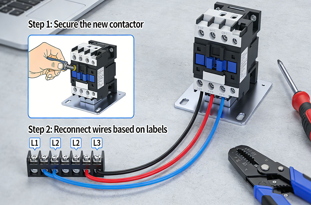
- Installation and Wiring: Secure the new contactor in place and reconnect all wires based on your previous labels, ensuring every terminal is tightened to specification.
- Functional Testing: Restore power to the control circuit and verify that the contactor pulls in smoothly without any abnormal arcing or vibration.
Identifying Critical Failure Symptoms
Early diagnosis of contactor failure can prevent total system breakdown. Look for these key warning signs:
- System Failure: The HVAC or industrial motor refuses to start despite receiving a signal from the controller.
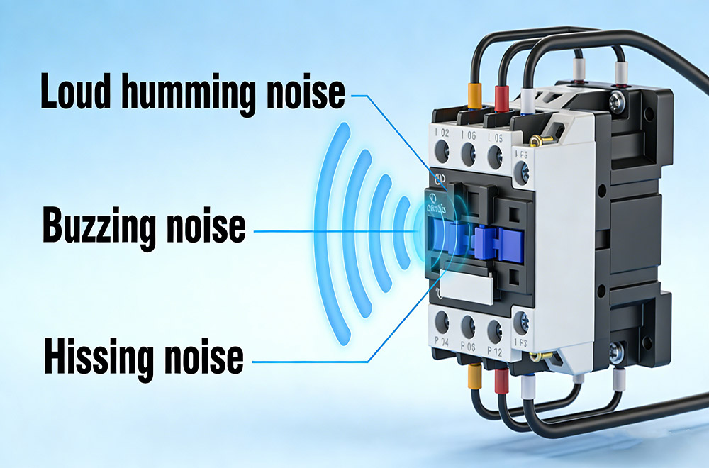
- Audible Indicators: Loud humming, buzzing, or hissing noises emanating from the contactor during operation.
- Continuous Running: The outdoor condenser unit or motor runs non-stop, indicating the contacts have welded or “stuck” in the closed position.
- Physical Degradation: The contactor casing appears melted, discolored, or emits a scorched plastic odor.
- Efficiency Drop: A sudden, unexplained spike in electricity bills or the system blowing warm air instead of cooling.
How to Safely Test an AC Contactor
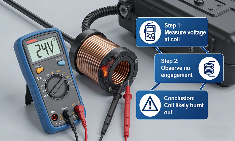
Safety is the paramount concern when performing electrical tests, so always ensure the power is disconnected before beginning. Use a multimeter to check the voltage between the L1 and L2 terminals, and if power is present, proceed to verify the integrity of the coil at the A1 and A2 terminals. A functional normally open (NO) contactor should show high resistance when de-energized, while a normally closed (NC) model should show a reading near zero.
You can further test the mechanical engagement by setting your thermostat to cooling mode and listening for the physical movement of the armature. If 24 volts are reaching the coil but no engagement occurs, the coil is likely burnt out.
Don’t forget to check for loose connections by gently tapping the terminals while monitoring your meter, as a fluctuating reading indicates a need for tightening rather than a full replacement.
Reasons for Non-Engagement and Solutions
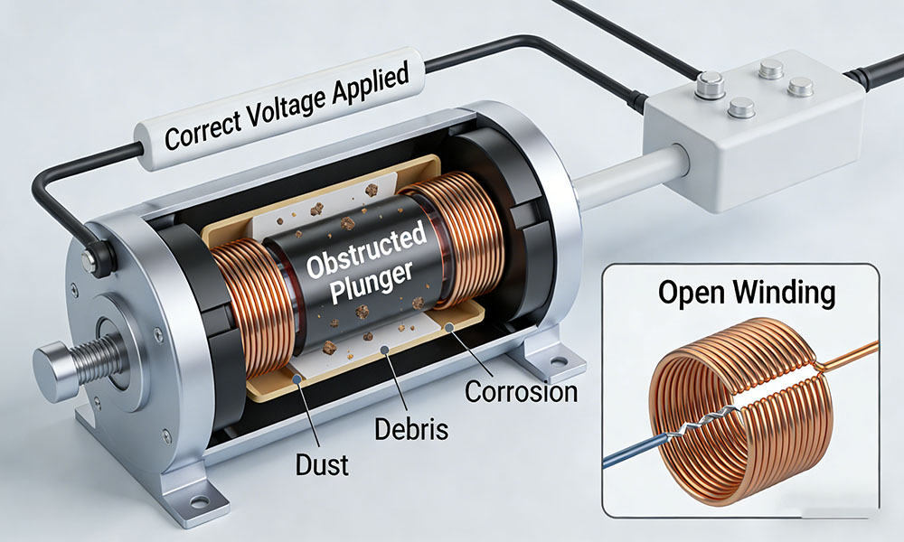
If a contactor refuses to engage, the issue is often rooted in a lack of signal from the control system rather than a mechanical failure of the contactor itself.
You should first verify the 24V control line. If no voltage is detected, the problem usually lies with the thermostat or the control board. If the coil is receiving the correct voltage but fails to actuate, the internal plunger may be obstructed by dust, debris, or corrosion, or the coil winding may be open. While manually pushing the plunger can serve as a temporary diagnostic to see if the load engages, this is never a permanent fix. For long-term reliability and safety, cleaning terminals or attempting a manual bypass is insufficient, and replacing the faulty AC contactor is the only recommended solution.
AC Contactor Selection Guide
| Selection Factor | Guidelines & Technical Requirements |
| Utilization Category | Distinguish between AC-3 for inductive motor loads (frequent starting/stopping) and AC-1 for resistive loads (heating, lighting). |
| Current & Voltage | Ensure the rated current matches the load. For motors, it is highly recommended to include a 20% safety margin to handle inrush currents. |
| Number of Poles | Use 2P for single-phase systems and 3P for standard three-phase industrial equipment. |
| Control Voltage | Select 24V for high-safety automation systems (PLC/SCADA) or 220V for simplified, direct-line wiring. |
| Global Certifications | For export projects or industrial compliance, verify that products hold UL, CE, or CB certifications to meet international safety standards. |
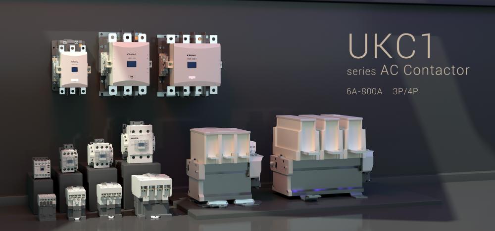
| Specialized HVAC Use | For air conditioning systems, specialized units like the KRIPAL UKC1 are preferred for their balance of performance and space efficiency. |
- Engineering Principles: Ensure long-term reliability through precise Load Matching (AC-3 for motors to prevent contact welding) and Voltage Coordination between control coils and power sources.
- International Standards: Global trade mandates compliance with IEC 60947-4-1, UL listing for North America, and CE marking for European safety and compatibility.
KRIPAL delivers a comprehensive, certified portfolio (6A–800A) tailored for diverse industrial needs. Our flagship UKC1 series excels in heavy industry and space-sensitive HVAC applications, offering compact, high-insulation designs. For cost-effective requirements, the UKC5 series serves as a reliable, economical switching solution.
Final Thoughts
AC contactors are the backbone of modern electrical infrastructure. Choosing the right component is more than just a purchase—it is an investment in the safety, efficiency, and longevity of your operations. Whether you are replacing a worn-out unit or designing a new industrial control system, prioritizing precise technical specifications, global certifications, and brand reliability is essential to ensuring your power runs smoothly and without interruption.
Frequently Asked Questions (FAQs)
Q1: Can AC contactors be used for DC applications?
No. AC contactors are engineered specifically for alternating current systems. Unlike AC, DC circuits do not have a natural current zero point, which makes extinguishing an electrical arc significantly harder. Using an AC-rated device for DC loads can lead to catastrophic failure and fire hazards.
Q2: What is the average lifespan of an AC contactor?
On average, a high-quality contactor is rated for 500,000 to several million cycles. However, its actual operational age is dictated by the environment and load matching. Adhering to proper ratings, maintaining clean contacts, and avoiding extreme heat can substantially extend its life.
Q3: Can an AC contactor be overridden manually?
Some models feature a manual override or test button, allowing technicians to temporarily engage the system for diagnostic purposes without automation. However, this should only be performed with extreme caution by qualified personnel, particularly in high-power systems.
Q4: What is the most common reason for contactor failure?
The primary causes are coil burnout (due to voltage fluctuations) and contact welding or pitting (caused by excessive inrush current or improper load matching). Environmental factors like dust and moisture can also accelerate mechanical failure.
Q5: What do A1 and A2 mean on a contactor?
These labels designate the coil terminals. A1 and A2 are where you connect the control voltage to energize the internal electromagnet and actuate the main contacts.
Q6: What are 13 and 14 on a contactor?
These numbers typically represent the Normally Open (NO) auxiliary contacts. These are used for control logic, such as providing a feedback signal to a PLC or powering a “system running” indicator light.
Related Resources
Explore News >
How can we assist you?
Tell us a bit more so we can route your request to the right expert.