Search
News
Circuit Breakers for Power Distribution Panels
Circuit breakers inside these panels are the devices that turn this structure into a safe and controllable system. Understanding how they work and how to choose them helps you design stable power distribution protection in low voltage panels.
![]() November 03, 2025
November 03, 2025
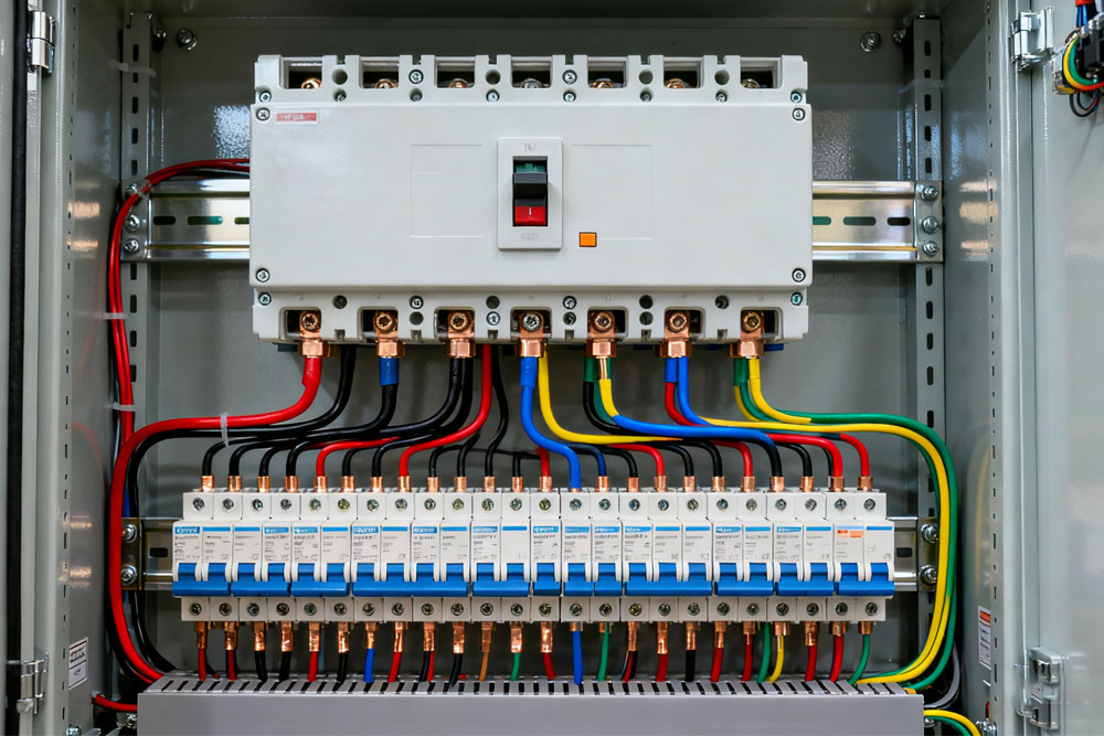
Power distribution panels, also called distribution boards or panelboards, sit at the center of a low-voltage system. They receive power from the upstream source and divide it into many outgoing circuits.
Circuit breakers inside these panels are the devices that turn this structure into a safe and controllable system. Understanding how they work and how to choose them helps you design stable power distribution protection in low voltage panels.
What Power Distribution Panels Do
A typical low voltage panel has three basic parts. The incoming section connects to the transformer or main switchboard. The busbar section carries current through copper or aluminum bars. The outgoing section contains rows of circuit breakers that feed branch circuits and subpanels.
Power flows from the incoming breaker into the busbars and then into each outgoing breaker. Every panelboard breaker protects one part of the system and allows it to be isolated when needed.
Roles of Circuit Breakers in LV Panels
Protection of cables and equipment
In a distribution board circuit breakers are more than simple switches. One key function is to protect cables and equipment from overload and short circuit faults by opening the circuit when current exceeds a defined level. This prevents overheating, insulation damage and loss of service life in connected devices.
Safe isolation for maintenance
Another function is to act as clear isolation points so maintenance staff can safely work on a feeder or final circuit with power removed and visible status. When the breaker is in the open position and properly locked, technicians can confirm that the circuit is separated from the live busbar and carry out inspection or repair with far lower risk.
Support for selectivity in the system
A third function is to support selectivity in the system. A fault in one branch should trip only the breaker serving that branch while other circuits in the panel keep running.
To achieve this, panels normally use a mix of breaker types. Main and feeder positions are often protected by molded case circuit breakers. Final circuits are usually protected by miniature circuit breakers. Residual current or earth leakage devices are added where people protection and leakage monitoring are required.
Typical Breaker Positions in a Distribution Panel
The table below shows a simple view of how different breakers are usually arranged inside a low voltage distribution panel.
| Type | Position in panel | Typical use |
| Main MCCB or ACB | Incoming section | Protection and isolation for the entire panel |
| Feeder MCCB | Outgoing section | Supply for subpanels, large motors, or special loads |
| MCB | Final circuit rows | Lighting, sockets, small equipment loads |
| RCD or RCBO | Selected final rows | Earth leakage and people protection on specific circuits |
By combining these levels the designer builds a protection hierarchy. The main device looks after the whole panel, feeder breakers protect large downstream groups, and small breakers protect individual loads.
Key Factors When Choosing Panelboard Breakers
To make selection more structured you can follow a simple checklist.
- Define panel voltage and system type such as single phase or three phase and choose breakers with matching or higher voltage rating.
- Calculate continuous current for each feeder and final circuit. Select breaker ratings that carry this current with reasonable margin while matching cable size.
- Estimate the maximum short circuit current at the panel location. Make sure each breaker has a breaking capacity equal to or higher than this value.
- Decide which circuits need molded case breakers for higher current and which can use miniature breakers for smaller loads.
- Plan selectivity so that downstream breakers clear faults before the main or feeder breaker trips. Use trip curves or adjustable electronic trip units where required.
- Check mounting type, terminal style and space inside the enclosure so that the breaker can be installed and serviced easily.
This step by step approach links electrical calculations to real products and to the physical layout of the panel.
Coordination and System Behavior
Coordination means that a fault should be cleared as close as possible to its source. In a power distribution panel this usually means that a final circuit breaker opens first. The feeder breaker should trip only if a fault is not cleared at branch level. The main breaker should operate only for faults that affect the entire panel or for very large faults that overload upstream equipment.
Good coordination brings two results. It limits the part of the system that loses power and it reduces stress on upstream breakers that would otherwise have to interrupt many more faults. In practice coordination is achieved by choosing proper current ratings, time delay settings on molded case breakers and appropriate curves for miniature breakers.
Mechanical Integration and Panel Design
Electrical ratings are only half of the job. Breakers must also integrate mechanically into the panel. Designers need to consider the width and height of each frame size, busbar connection methods, cable bending radius, door depth and the need for accessories such as shunt releases, undervoltage releases and auxiliary contacts.
A clean panel layout places the main breaker in an accessible position, feeds busbars with clear routing, and groups outgoing breakers logically by function or location. A good match between panelboard breaker design and the panel structure simplifies installation and improves safety during future modifications.
Summary
Circuit breakers inside power distribution panels form the backbone of low voltage power control. When device ratings, coordination and mechanical layout are planned together, the result is a panel that supplies power reliably and reacts to faults in a controlled and predictable way.
If you are designing or upgrading low voltage panels and want breakers that match your distribution board, load profile and coordination plan, you can ask for a quote from Kripal. We supply professional grade panelboard breakers and distribution products supported by strong research, manufacturing and testing capability.
Related Resources
Explore News >


How can we assist you?
Tell us a bit more so we can route your request to the right expert.